Basic Service Documentation. Copyright General Electric Company.
Object ID: 00000018WIA30FBBF20GYZ
Topic ID: id_13106568 Version: 1.2
Date: Jul 6, 2019 12:17:31 AM
Front Bridge Assembly
Prerequisites
Table 1. Personnel requirements
Required persons
Preliminary requirements
Procedure
Finalization
2
Not Applicable
30-75 mins minutes
Not Applicable
Table 2. Tools and test equipment
Item
Quantity
Effectivity
Part number
Manufacturer
Non ferrous M17
wrench
1
-
-
-
Non ferrous M5 Allen
wrench
1
-
-
-
Non ferrous Phillips
screwdriver
1
-
-
-
Non ferrous Flathead
screwdriver
1
-
-
-
Table 3. Replacement parts
Item
Quantity
Effectivity
Part number
Manufacturer
Front Split Bridge 5333192
1
systems only replacing the
bridge itself. In using this replacement part, you will have to reuse
the currently installed front pulley and drive belt. See
-
-
Front Bridge ASM with Pulley and Belt 5333181
1
systems replacing the bridge
and its accessories, including pulley and drive belt.
-
-
Table 4. Safety
Warning
FERROUS MATERIAL HAZARD!!
THE PULLEY ASSEMBLY CONTAINS PARTS MADE WITH FERROUS COMPONENTS.
HOLDING THIS ASSEMBLY TOO CLOSE TO THE MAGNET BORE WILL FORCIBLY ATTRACT
IT TO THE MAGNET.
TO PREVENT POSSIBLE BODILY INJURY, OR DAMAGE TO COMPONENTS,
REMOVE THE ASSEMBLY DIRECTLY, NOT MOVING IT IN THE MAGNETIC FIELD
MORE THAN IS NECESSARY.
Warning
FERROUS MATERIAL HAZARD!!
THE FRONT BRIDGE SUPPORT ASSEMBLY CONTAINS PARTS MADE WITH
FERROUS COMPONENTS. HOLDING THIS ASSEMBLY TOO CLOSE TO THE MAGNET
BORE WILL FORCIBLY ATTRACT IT TO THE MAGNET.
TO PREVENT POSSIBLE BODILY INJURY, OR DAMAGE TO COMPONENTS,
REMOVE THE ASSEMBLY DIRECTLY, NOT MOVING IT IN THE MAGNETIC FIELD
MORE THAN IS NECESSARY.
About this task
Procedure for replacing the patient transport split bridge.
Plan on about 30 minutes to remove the bridge. Double the time if
you are reinstalling the same bridge components. Plan on at least
75 minutes if you are installing a new bridge that has to have the
subcomponents assembled (see Replacing Bridge with Part Number 5555192).
Removing Front Bridge
Procedure
Move the LPCA to rear pedestal with IN button of magnet front
panel. Then, Separate LPCA from cradle.
Move the Cradle to the home position and undock the patient
table.
Release drive belt tension by flipping lever under rear pedestal.
Figure 1. Belt Tension Arm
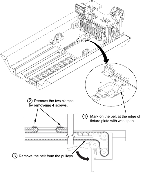
Remove the two belt clamps of from LPCA. Refer to illustration.
(see Figure 2)
Remove the belt from the pulleys of rear pedestal.
Figure 2. Note the number of Belt Notches beyond the Belt Clamp
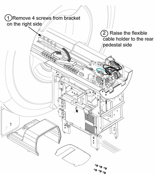
Remove the flexible cable holder from the front split bridge
by removing 4 screws.
Raise the flexible cable holder to the rear pedestal side. Refer
to illustration.
Figure 3. Raise the flexible cable holder
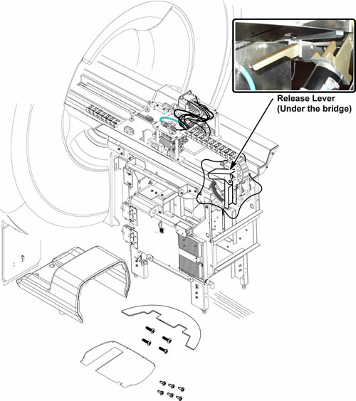
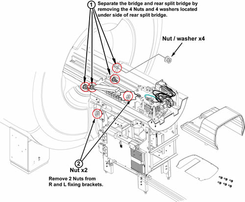
Separate bridge from rear split bridge by removing 4 nuts and
4 washers and removing 2 nuts from R and L fixing brackets.
Figure 4. Separate bridge from rear split bridge
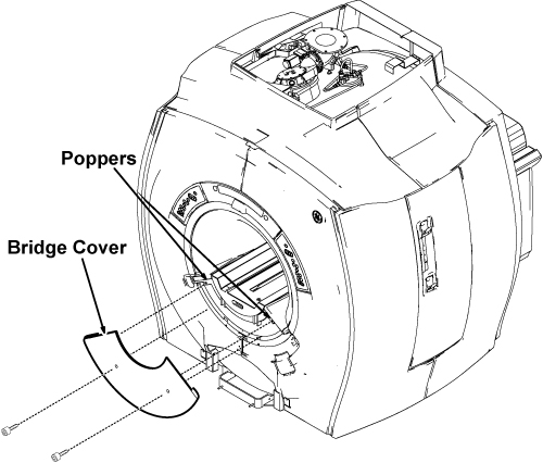
Remove the bridge cover by removing two M5 bolts.Figure 5 shows the procedure for SIGNA MR360 Configure, for SIGNA MR355 configure, uninstall the fixed table first following the procedure in Fixed Table Replacement, and then follow the same procedures shown in Figure 6
Figure 5. Lower Cosmetic Cover
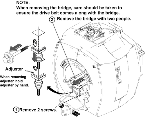
CAUTION
The bridge weight is approx 23kg. The bridge removal needs
two people to damage prevention for enclosure bore. When the removing
the bridge, care should be taken to ensure the drive belt comes along
with the bridge.
Remove the bridge from the magnet bore.
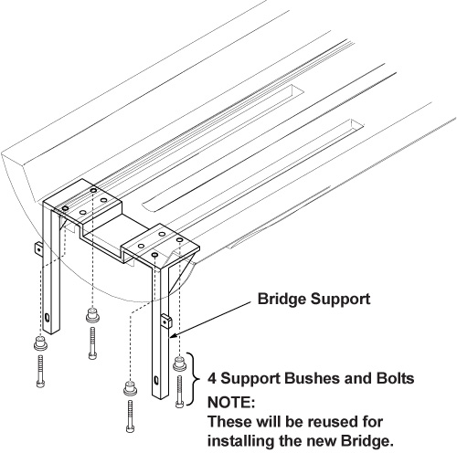
Figure 6. Bridge Bracket Height Adjustor and Spacer
Note:
If you are going to put this bridge back, do not change
the location of the Height Adjustment's threaded nylon nuts. If you
are replacing this bridge with a new bridge, adjust the lower nuts
so the edge of the bridge adjacent to the end bell is 2-4 mm above
the flat surface of the end bell.
Figure 7.
Slide the bridge out from magnet. Care should be taken to ensure
the drive belt comes along with the bridge.
Replacing Bridge with Part Number 5555192
Procedure
Lay bridge on its top and remove the four (4) M5 Allen bolts
that attach the Bridge Mounting Bracket.
Figure 8. Bridge Bracket Bolt Locations
Remove belt from bridge.
Figure 9. Pulley with Belt Removed
Warning
FERROUS MATERIAL HAZARD!!
THE PULLEY ASSEMBLY CONTAINS PARTS MADE WITH FERROUS COMPONENTS.
HOLDING THIS ASSEMBLY TOO CLOSE TO THE MAGNET BORE WILL FORCIBLY ATTRACT
IT TO THE MAGNET.
TO PREVENT POSSIBLE BODILY INJURY, OR DAMAGE TO COMPONENTS,
move the bridge out of the magnetic field before continuing.
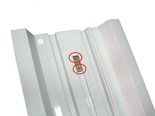
Flip the bridge so the top is facing up. Using a regular screwdriver,
unscrew the two bolts.
Figure 10. Screw Location
Note:
When these bolts are removed, the plate on the opposite
side will fall out.
To reinstall the bridge, perform the steps in Removing Front Bridge in reverse order.
Finalization
Procedure
Dock the Table and move the Table to the up limit position.
Verify that the Table and Bridge are horizontally aligned and there
is no height difference of Table and Bridge at right and left position.
Verify that Cradle moves in and out fully and smoothly.

 Note:
Note: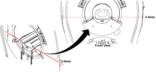
 Note:
Note: