- SIGNA MR355 / SIGNA MR360
- Service Manual
- 5856356-3EN Revision 5.0
- Basic Service Documentation. Copyright General Electric Company.
- 00000018WIA30A31030GYZ
- id_131061021.4
- Apr 23, 2020 7:22:12 PM
MCS Replacement
Prerequisites
| Required persons | Preliminary requirements | Procedure | Finalization |
|---|---|---|---|
| 1 | Not Applicable | 90 minutes | 15 minutes |
| Item | Quantity | Effectivity | Part number | Manufacturer |
|---|---|---|---|---|
| Standard Tool | 1 | - | - | - |
| Miniature ratchets for MCS site. (It is required for cable wiring in MCS) | 1 | - | - | - |
| 20L Draining Tank | 2 | - | - | - |
| 5L Draining Tank | 1 | - | - | - |
| Water Hand Pump | 1 | - | - | - |
| 150MM FUNNEL | 1 | - | - | - |
| WATER HOSE SET (500 mm Hose) | 2 | - | - | - |
| HOSE BAND 1 | 2 | - | - | - |
| Tie Wraps(20cm or longer) to fold and bind the hose of LCS/MCS to prevent from draining. | 4 | - | - | - |
| Unused newspaper or cloth to trap the drained coolant. | 1 | - | - | - |
| Plastic draining tank. (Stored under water manifold at System Cabinet left side.) | - | - |
1 | - |
| Item | Quantity | Effectivity | Part number | Manufacturer |
|---|---|---|---|---|
| MCS (Refer to Lockout / Tagout for System Cabinet PDU Main Breaker) | 1 | - | - | - |
| ||||
| Condition | Reference | Effectivity |
|---|---|---|
|
By this replacement, 200ml of coolant for system cabinet will be decreased. Please consider the coolant level of MCS which was checked during PM. If necessary, prepare coolant water 5L (5159818). | - | - |
|
System Power must be turned OFF. Refer to Lockout / Tagout for System Cabinet PDU Main Breaker. | - | - |
Procedure
- Close the IN/OUT valves of water manifold.
Figure 1. Water Manifold Access Cover and IN/OUT Valves 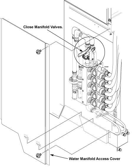
- Remove R side cover of MCS by removing 2 screws.
Figure 2. Cover Removal of MCS 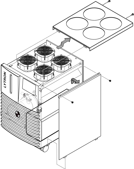
- Drain the all coolant from MCS tank.
Figure 3. Setting of Coolant Draining 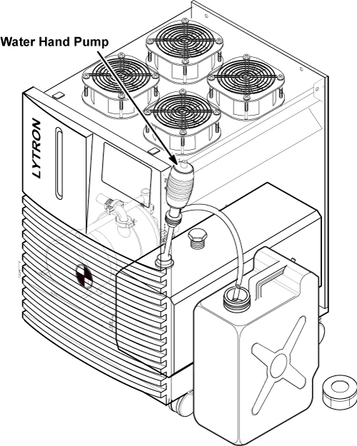
- Before removing the hoses from MCS, fold and bind each hose
to prevent from draining. Spread unused news paper for cloth on the
floor.
Figure 4. BIND EACH HOSE 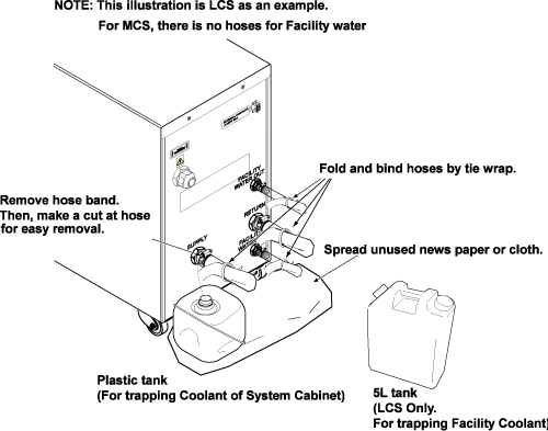
- Disconnect hoses from MCS rear panel.Note:
When removing the hose easily, make a cut at the hose opening.
Figure 5. Removal of hose 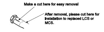
- Note:Connect 500 mm hose to inlet and outlet of MCS with clamps.
Be careful the coolant does not spill to floor. If needed, use funnel and 5L tank.
Figure 6. Hose Setting of MCS Rear Panel 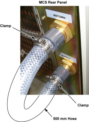
Finalization
Procedure
- Verify that LED on Reverse Phase Repay is NOT lit while MCS/LCS is running.
Figure 7. LED on Reverse Phase Repay 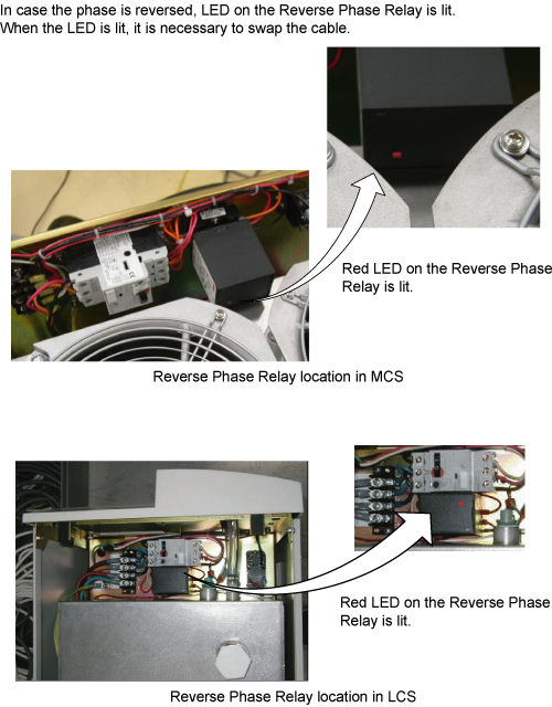
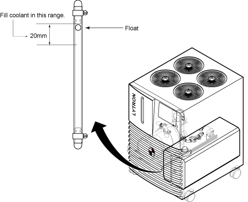
- Check the coolant level by checking that the float is in the range. Refer to Figure 8.
Figure 8. Coolant Range