
- SIGNA MR355 / SIGNA MR360
- Service Manual
- 5856356-3EN Revision 5.0
- Basic Service Documentation. Copyright General Electric Company.
- 00000018WIA309A1030GYZ
- id_131073131.1
- Jul 5, 2019 11:49:10 PM
Replacement of SRI (Scan Room Interface)
Prerequisites
| Required persons | Preliminary requirements | Procedure | Finalization |
|---|---|---|---|
| 1 | Not Applicable | 30 minutes | Not Applicable |
| Condition | Reference | Effectivity |
|---|---|---|
|
System Power must be turned OFF. Refer to System Cabinet PDU Main Breaker LOTO Procedure. | - | - |
About this task
The SRI Assembly is located under the right side of the magnet enclosure.
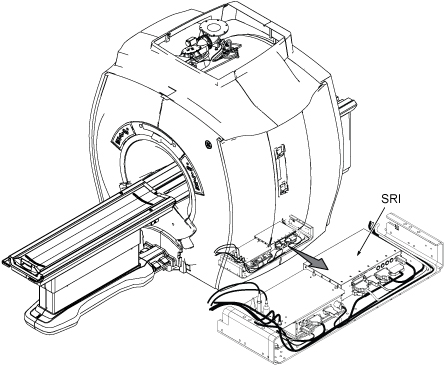
Removal of SRI
Procedure
- Remove bottom bar from Magnet right side.
Figure 2. Removing bottom bar 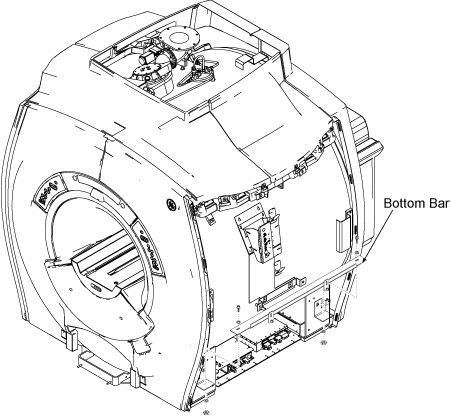
- Remove SRI from PAC/SRI tray. The SRI is installed by Velcro
tape to tray.
Figure 3. SRI Removal 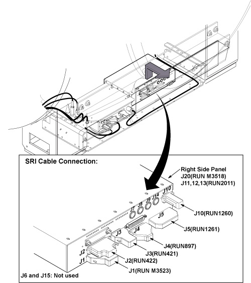
Installation of New SRI
Procedure
- Place new SRI on tray.
- Connect the all cables.
- Fix the cables with tie-wraps.
- Restore bottom bar.
- Restore side covers.
- Remove tag-out tag from circuit breaker.
- Restore power.
Finalization
Procedure
- Perform SRI functional Check.
- Perform each test and verify that the each function works ok.
Figure 4. SRI Functional Check 
- Perform each test and verify that the each function works ok.
- Perform Signal to Noise - Head Scan.