Personal injury and equipment damage
Strong Magnetic Field
When servicing any magnetic equipment, it is critically important that the service engineer consciously plan the path to be taken when moving highly ferrous devices in the magnet environment. the path should be as far from the magnet as practical and avoid high flux-density fields.
Safety Requirements
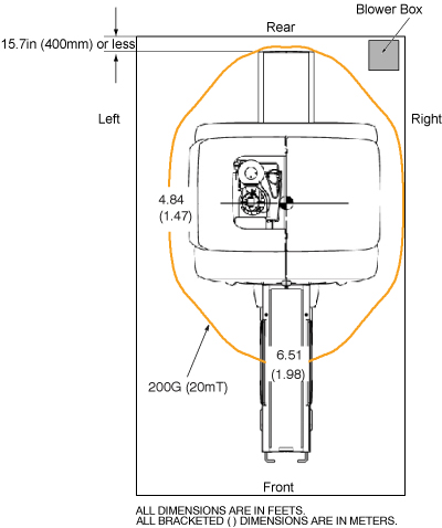
Movement of ferrous material in the magnet room must follow the GE service procedure for that device. When exiting, move away from the magnet in the most direct manner possible. Except when moving ferrous material to and from its native location on or near the magnet, the static magnetic field in any portion of the service path shall not exceed 200 Gauss.
Two (2) MR safety trained personnel must be present at all times when servicing highly ferrous devices in the areas of magnetic fields.
When planning a service path, it is critical that the path be clear and sufficiently wide. Ensure that there are no trip hazards, obstacles, clutter, slippery surfaces or other items even partially restricting the path. If there are portable obstacles in a path, remove them from the area and replace them after the service action is completed. It is required to walk the path prior to beginning service to ensure that there is sufficient space through which to pass for yourself and the object being serviced.