
- SIGNA MR355 / SIGNA MR360
- Service Manual
- 5856356-3EN Revision 5.0
- Basic Service Documentation. Copyright General Electric Company.
- 00000018WIA30401030GYZ
- id_131060961.3
- Jul 5, 2019 10:46:04 PM
Laser Light Replacement
Prerequisites
| Required persons | Preliminary requirements | Procedure | Finalization |
|---|---|---|---|
| 1 | minutes | minutes | minutes |
 | ||||
About this task
Overview
Procedures for replacing alignment lights, and alignment of the laser lights. There is one (1) laser light in the top middle assembly.
Laser Light Removal
Procedure
- Slide laser light out of housing. See Figure 1.
Figure 1. LASER ALIGNMENT LIGHT ASSEMBLY 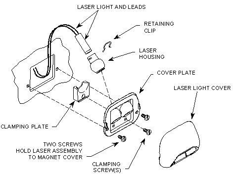
Laser Light Replacement
Procedure
- Plug new laser light into power supply board.
- Slide housing onto laser and install retaining clip. See Figure 1.
- Install clamp and slotted screw onto cover plate. See Figure 1.
- Install cover plate to magnet front end bell using two furnished screws. See Figure 1.
- Reinstall the center control panel.
- Refer to the corresponding Lockout/Tagout power restoration process.
- Turn on laser alignment lights and check alignment of replaced laser. Refer to Laser Light Alignment for procedure on how to properly align the laser lights.
Finalization
Procedure
- Perform any scan to obtain the coronal image. Check that the phantom image is at the center of display.
- Perform DQA II Tool to adjust Iso-Center Z.
- Perform Signal to Noise - Head Scan.