
- SIGNA MR355 / SIGNA MR360
- Service Manual
- 5856356-3EN Revision 5.0
- Basic Service Documentation. Copyright General Electric Company.
- 00000018WIA301DFF20GYZ
- id_131073791.2
- Jul 5, 2019 10:25:10 PM
ECG Leads Checks
Prerequisites
| Required persons | Preliminary requirements | Procedure | Finalization |
|---|---|---|---|
| 1 | Not Applicable | 15 minutes | Not Applicable |
About this task
All the of the ECG clip leads are connected together. The right leg (RL) lead supplies a +2.5Vdc drive signal to the right arm (RA), left arm (LA), and left leg (LL) leads. The signal from each of these leads is read and checked to ensure that their respective inputs to the ECG A/D converter are in the +2.5V ± 200mv range. If any of them are not in this range, an error message is entered in the message log. If the signals from the RA, LA, and LL leads are all out of range, it is assumed that the RL lead has failed.
Procedure
- Connect the cardiac gating lead to the Physical Acquisition
Controller (PAC) Assembly as shown in Figure 1.
Connect the clip leads to the test points on the PAC (the test points
are all shorted together). The clips leads are color-coded: Red is
LL, White is RA, Black is LA, and Green is RL.
Figure 1. PAC ASSEMBLY WITH ECG LEADS CONNECTED 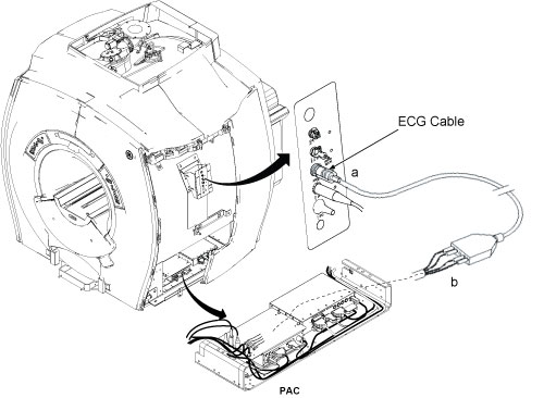
- Refer to Figure 2 for starting ECG
Lead Test.
Figure 2. Starting PAC Diagnostics 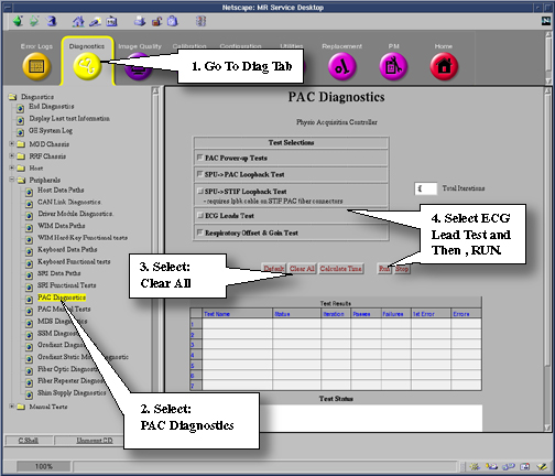
Finalization
- Restore Magnet Enclosure.
- Put the system back in patient scanning condition.
- Do a check scan to insure the system is operating properly.