
- SIGNA MR355 / SIGNA MR360
- Service Manual
- 5856356-3EN Revision 5.0
- Basic Service Documentation. Copyright General Electric Company.
- 00000018WIA30EBBF20GYZ
- id_131061001.1
- Jul 6, 2019 12:17:31 AM
Rear End Bell Removal
Prerequisites
| Required persons | Preliminary requirements | Procedure | Finalization |
|---|---|---|---|
| 1 | Not Applicable | 1.5 hours | Not Applicable |
| Item | Quantity | Effectivity | Part number | Manufacturer |
|---|---|---|---|---|
| Non ferrous M5 Allen Wrench | 1 | - | - | - |
| Non ferrous M4 Allen Wrench | 1 | - | - | - |
| Non ferrous Phillips Driver | 1 | - | - | - |
| ||||
| Condition | Reference | Effectivity |
|---|---|---|
|
System Power must be turned OFF. Refer to System Cabinet PDU Main Breaker LOTO Procedure. | - | - |
Procedure
- Remove the patient light end covers from the upper side of magnet
bore by removing 2 bolts.
Figure 1. Patient Light End Cover Removal 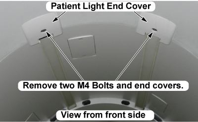
- Remove the patient lights from the magnet bore upper side. The
patient light is secured by Velcro tape.
Figure 2. 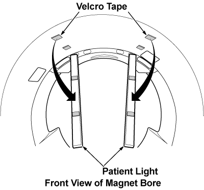
- Using an M5 Allen wrench, remove the two M6 bolts of fasteners
which connect the RF coil and the rear end bell. (Refer to illustration
3)
Figure 3. Hose and Fixing Bolts Removal 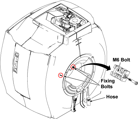
- Remove the cable cover from the rear end bell by removing 2
screws.
Figure 4. 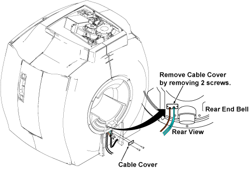
- Disconnect the OPT fiber cables from LED Power Box assembly.
(Refer to illustration 5.)
Figure 5. Disconnect OPT Cables 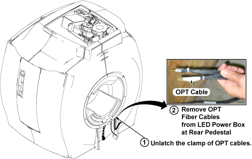
- Remove the 6 bolts (M10 x6) securing rear end bell to the magnet.Note:
Do not remove the rear end bell. The rear end bell is connected by speaker cable.
Figure 6. 6 Bolts Removal of Rear End Bell 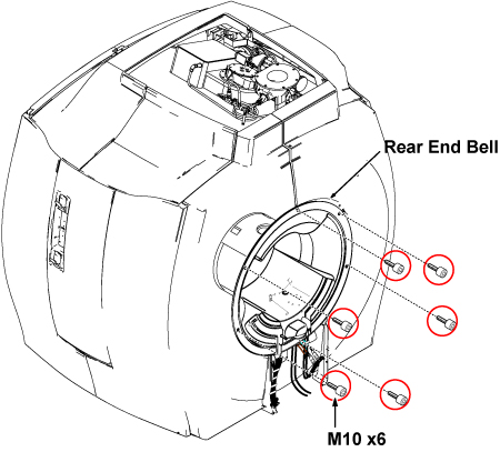
- Disconnect the speaker cable from the magnet upper side.
Figure 7. Disconnect Speaker Cable 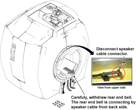
- Remove the rear end bell from the magnet bore.
Figure 8. Rear End Bell Removal 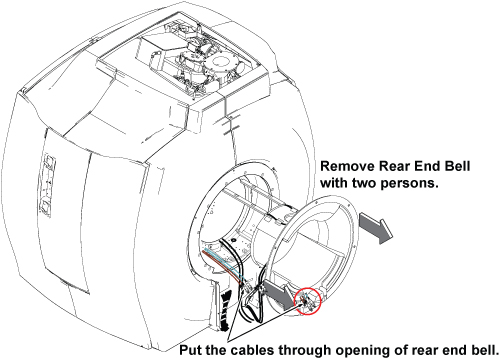
Finalization
No finalization steps.