- SIGNA MR355 / SIGNA MR360
- Service Manual
- 5856356-3EN Revision 5.0
- Basic Service Documentation. Copyright General Electric Company.
- 00000018WIA305CDF20GYZ
- id_131065213.0
- Feb 22, 2021 9:54:51 PM
Dell T5810 Computer Replacement
Prerequisites
| Required persons | Preliminary requirements | Procedure | Finalization |
|---|---|---|---|
| 1 | Not Applicable | 60 minutes | 120 minutes |
| Item | Quantity | Effectivity | Part number | Manufacturer |
|---|---|---|---|---|
| Screwdriver set | 1 | - | - | - |
| Disk Management Tool | 1 | - | - | - |
| Item | Quantity | Effectivity | Part number | Manufacturer |
|---|---|---|---|---|
| GE equipment maintenance sticker | 1 | - |
Refer to FRU manual | - |
| Item | Quantity | Effectivity | Part number | Manufacturer |
|---|---|---|---|---|
| Dell T5810 computer | 1 | - |
Refer to FRU manual | - |
| Dust filter (if needed) | 1 | - |
Refer to FRU manual | - |
| ||||
About this task
This procedure provides instruction to replace the host computer with a Dell T5810 computer.
Prepare Workstation for Host Computer Removal
Procedure
Remove Host Computer from GOC
Procedure
- Remove the two screws that secure the left side panel of the
GOC.Note: The side panel has a short ground lead connecting it to the main chassis. When removing the side panel, do not strain this ground lead.
Figure 1. Remove GOC Left Side Cover 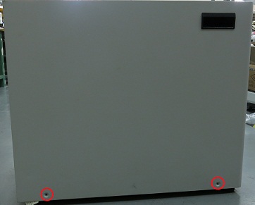
- Disconnect the short ground lead that connects the side panel
to the GOC main chassis at the center of the lead.
Figure 2. Left Side Panel Ground Lead 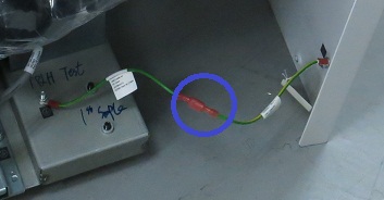
- Remove all the cables connected to the host computer.
Confirm that the cables are properly labeled. Note their locations for reattachment.
Figure 3. Dell T5810 Cable Configuration 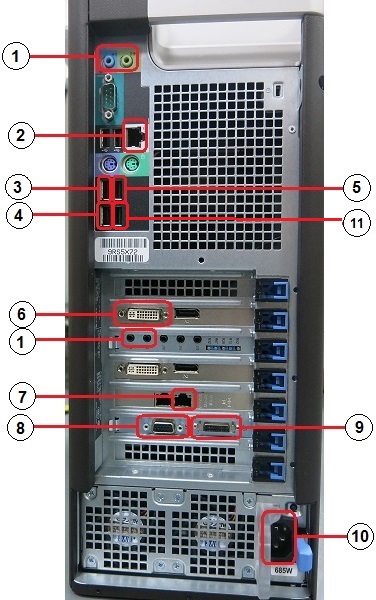
(1) PCI-AA (line in, line out) (7) To System Cabinet Top J63 (Run E3502) (2) Ethernet (8) To Penetration Panel J12 (Run E3503) (3) Keyboard USB cable (9) To SCIM (4) To System Cabinet Top J25 (Run E3037) Note: Connect this cable to USB 3.0 (10) Power supply (5) Mouse USB cable (11) To 1–wire Adapter (6) To LCD display Note:For older GOCs which include an 8-port hub, route and connect Ethernet cable from GOC hub to this port.
For newer GOCs without a hub, this port is available for connecting to a service laptop, site network, or AW option. If connection to multiple Ethernet devices is required, a customer-supplied switch must be used.
Install New Host Computer
Procedure
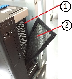
- Remove the dust filter (2) and Velcro strips (1) from the old
computer, and install them on the new computer. If the old filter
or Velcro strips are not reusable, install a new set.
Figure 4. Dust Filter