- SIGNA™ Hero 3.0T Service Methods
- 5852800-8EN Revision 1.0
- 00000018WIA3009E350GYZ
- id_20209571.19
- Aug 6, 2021 3:36:39 PM
Removing the P2/P4 cable assembly
Removes the P2/P4 cable track assembly from the dockable patient table.
Prerequisites
| Personnel requirements | |||
|---|---|---|---|
| Required persons | Preliminary requirements | Procedure | Finalization |
| 2 | - | 30 minutes | - |
| Tools and test equipment | |||
|---|---|---|---|
| Item | Quantity | Part number | Manufacturer |
| Nonmagnetic Titanium Service Tool Kit, Small Set | 1 | 5113258 | - |
| Required conditions |
|---|
| The P2/P4 cable is removed from the cradle. |
| The table side covers, base covers, bellows cover, front bumper, and lower front bumper are removed from the table. |
Procedure
Lower the table lock safety bar.Warning 
Figure 1. Lock safety bar down 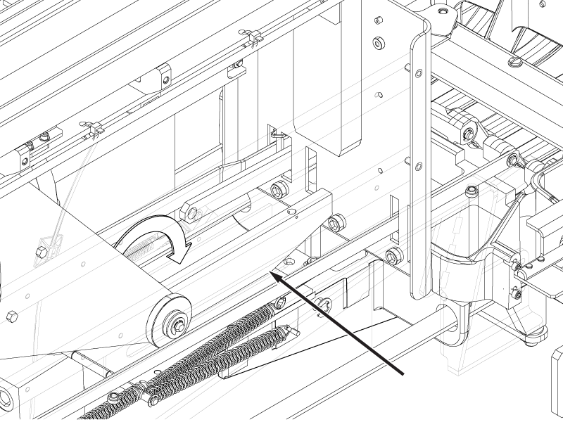
- Disconnect the P2 RF Tx cable from the P1 transmit connector.
Figure 2. P1 transmit connection 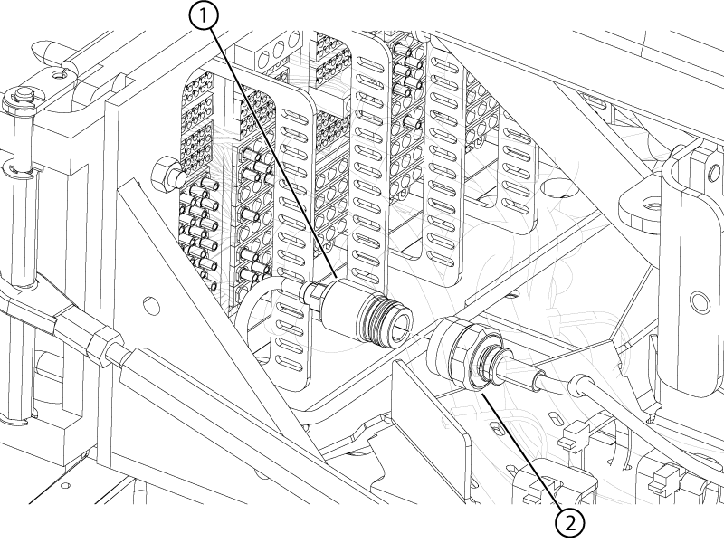
1 P2 RF Tx 2 P1 transmit - Disconnect the dummy load connector from the dummy load.
Figure 3. Dummy load connection 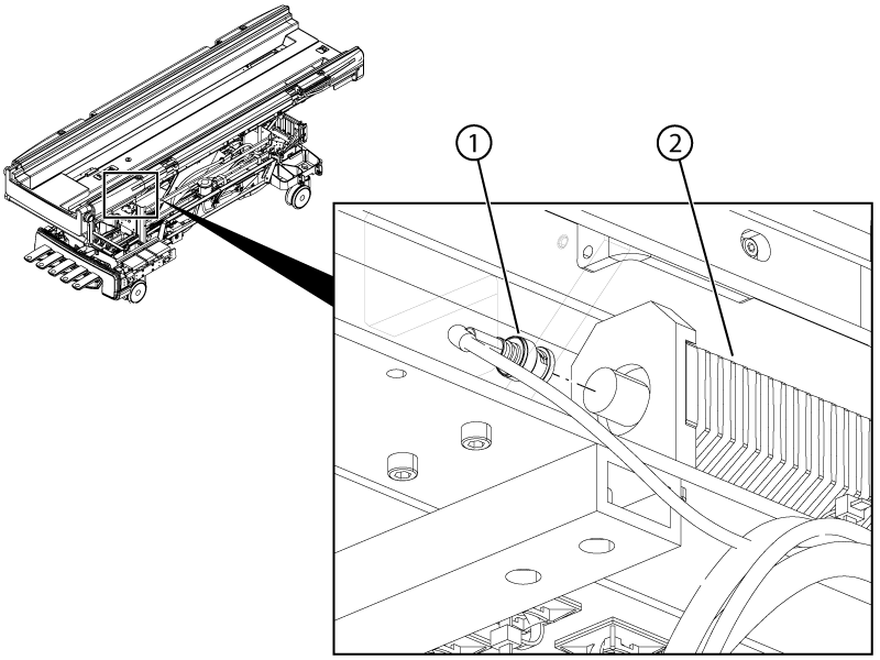
- Disconnect the motor power and motor signal cables from the motor assembly.
Figure 4. Motor power and signal connectors 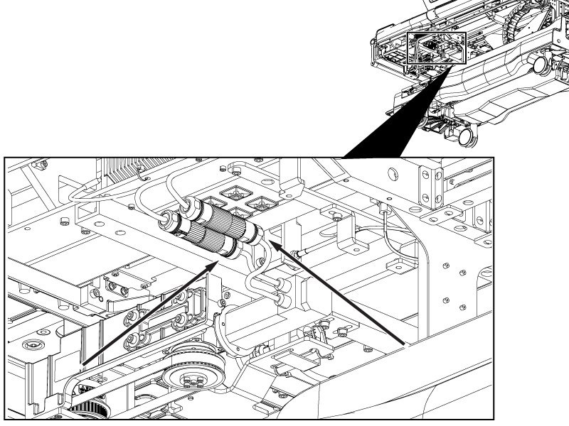
- Disconnect the following connectors from the Physiological Acquisition Controller (PAC):
- Electro-CardioGram (ECG)
- PAC fiber optic cable from J1
- Respiratory tube from J3
- Peripheral gating connectors from J5 and J6
- 1-wire & Hart ID from J9
- PAC power from J2
Figure 5. PAC connections 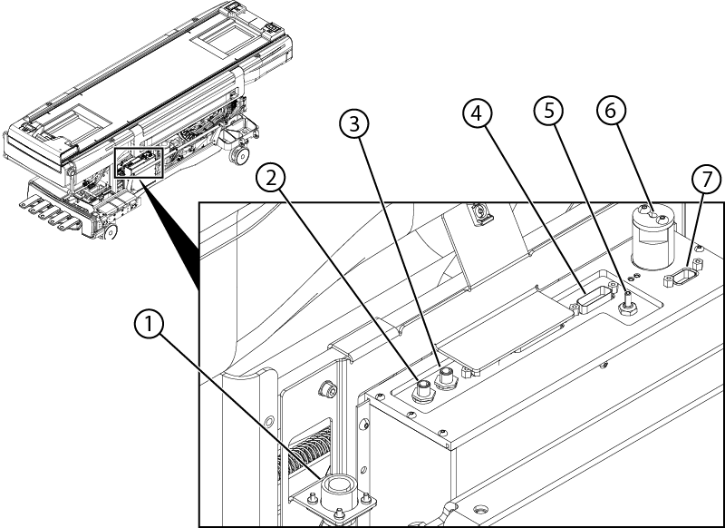
1 ECG cable PAC ECG connector 2 Peripheral gating J6 3 Peripheral gating J5 4 Power J2 5 Respiratory tube J3 6 Fiber optic J1 7 1-wire and HART ID J9 - Disconnect the P2 bone conducting headphone cable from the P1 ODU headphone connector.
Figure 6. P2 bone conducting headphone connection 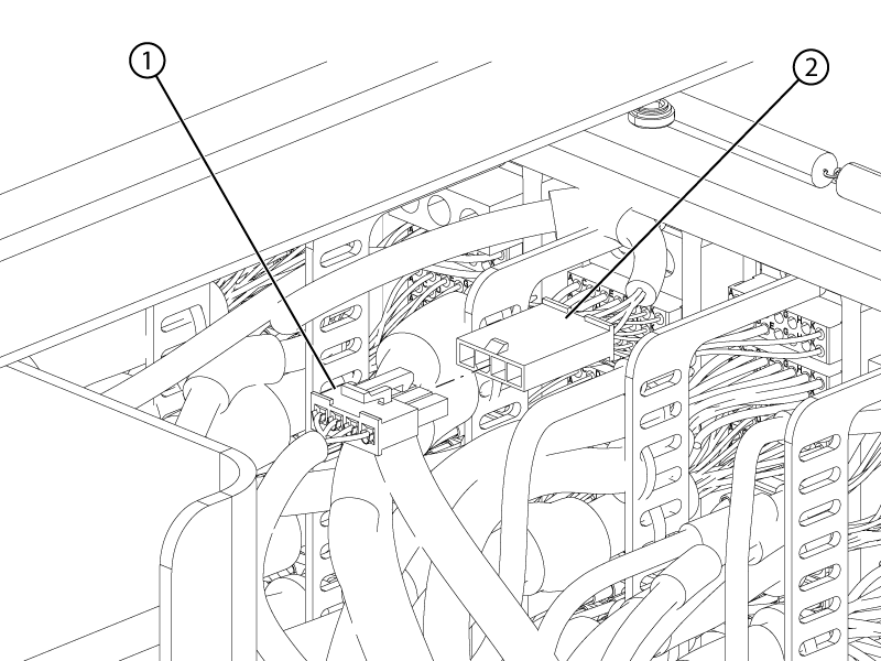
1 P2 bone conducting headphone 2 P1 headphone - Remove the two screws securing the base cover bracket to the table.Note: This bracket is being removed for better access to the ODU connectors.
Figure 7. Base cover bracket 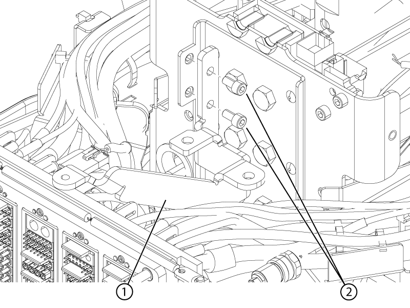
1 Bracket 2 Screws - Remove the patient alert tube from the P3 ODU connector.
Figure 8. Patient alert ODU connection 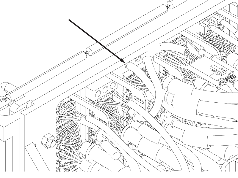
- Remove the four screws securing the P2 and P4 ODU connectors to the ODU plate (two screws per connector).
Figure 9. P2 and P4 ODU screws 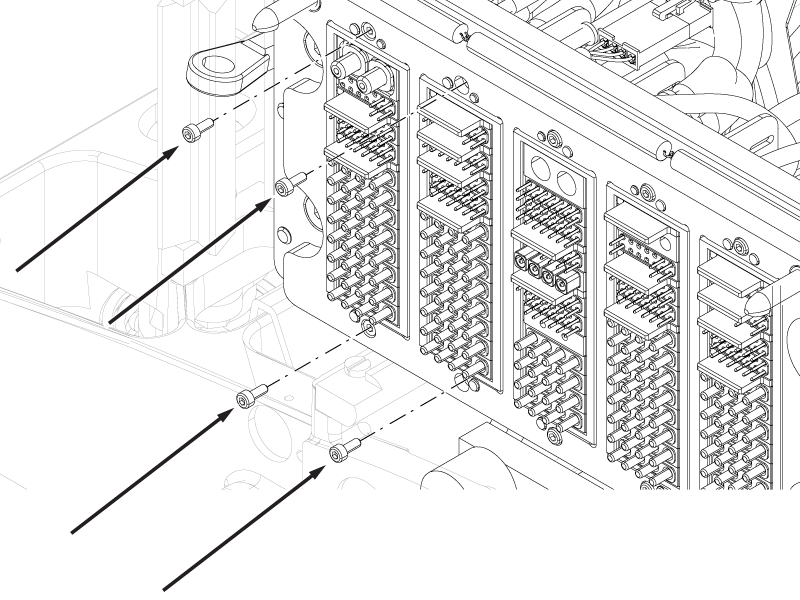
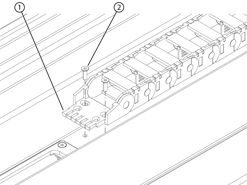
- Remove the two screws securing the right-hand lower cable track to the bottom of the tabletop.
Figure 10. Right-hand lower track upper screws 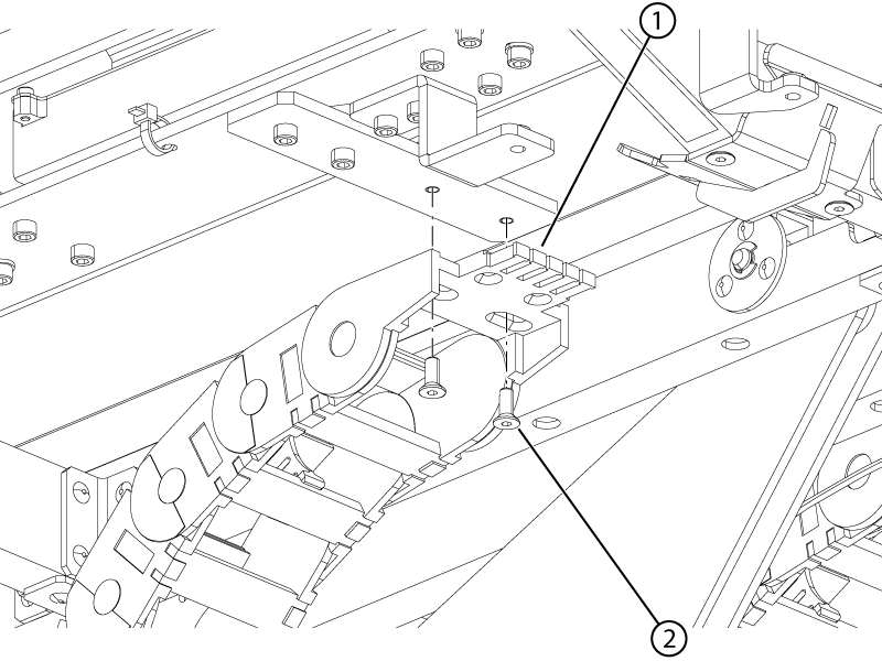
1 Cable track 2 Screw - Remove the two screws securing the right-hand lower cable track to the slider plate.
Figure 11. Right-hand lower track lower screws 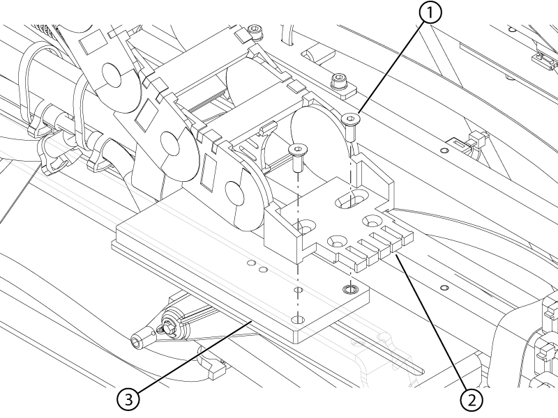
1 Screw 2 Cable track 3 Slider - Remove the two screws securing the right-hand cable protection plate to the tabletop.
Figure 12. Right-hand upper cable track protection plate 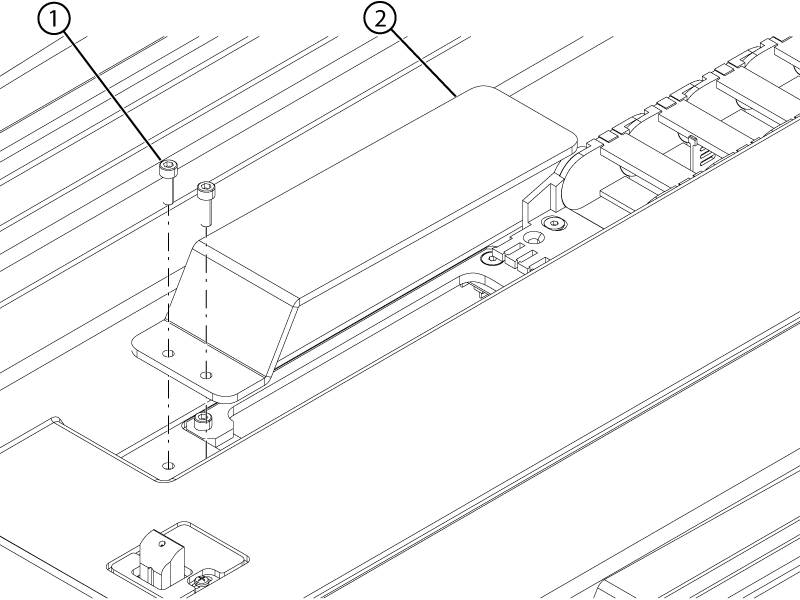
1 Screw 2 Protection plate - Remove the two screws securing the right-hand upper cable track to the top of the tabletop.
Figure 13. Right-hand upper track screws