- SIGNA™ Hero 3.0T Service Methods
- 5852800-8EN Revision 1.0
- 00000018WIA30AFC230GYZ
- id_156676231.52
- Jan 26, 2022 3:32:57 PM
VRMw coil replacement
Prerequisites
| Personnel requirements | |||
|---|---|---|---|
| Required persons | Preliminary requirements | Procedure | Finalization |
| 3 | - | 3 days | - |
| Tools and test equipment | |||
|---|---|---|---|
| Item | Quantity | Part number | Manufacturer |
| Nonmagnetic Hand Air Pump | 1 | - | - |
| Extension Cord | 1 | - | - |
| Vacuum Cleaner | 1 | - | - |
| Set: Nonabsorbent Protective Clothing (long sleeve shirt and pants) | 1 for each person | - | - |
| Pair: Nonferrous Safety Shoes | 1 for each person | - | - |
| Safety Glasses | 1 for each person | - | - |
| Pair: Cut-Resistant Gloves | 1 for each person | - | - |
| Gradient Coil Cart | 1 | 2134810 | - |
| Gradient Coil Insertion and Lift Kit | 1 | 2164744-8 | - |
| Universal Field Mapping Fixture Kit | 1 | 5266042-4 | - |
| Nonmagnetic Titanium Service Tool Kit, Large Set | 1 | 5112581 | - |
| Torque Wrench, 8-50 N m Adjustable, non-magnetic | 1 |
5534134 or 5534134-2 | - |
| B0 Power Supply Kit | 1 | 2141701 | - |
| 5 Gallon Pail | 1 | 2239133 | - |
| Dispenser of 100 #6005 Large N-DEX Nitrile Disposable Gloves Best #6005L | 1 | 46-194427P400 | - |
| Authorized Personnel Floor Sign (included with Safety Signage Kit 46-258770G4) | 1 | 2289812 | - |
| Magnet & Cryogen Manual - Passively Shimmed Magnets (Download from Online Document Library) | 1 |
5495018 | - |
| Consumables | |||
|---|---|---|---|
| Item | Quantity | Part number | Manufacturer |
| Isopropyl Alcohol, 70%, USFS-200 | 1 | - | - |
| Scour Pad (or equivalent) | As Required | - | Scotch-Brite™ |
| Cable Tie, 190 Wide X 14 large, nylon | 100 | 46-252283P68 | - |
| Loctite #243 (check expiration date) | 1 | 5415261-3 | - |
| Loctite 271 (check expiration date) | 1 | 46-170684P2 | - |
| Never Seize | As Required | 46294151P8 | - |
| Clean Lint-Free Towels (Kimwipes™) | As Required | - | - |
| Coolant (Note: Coolant will be reused. According to the remaining coolant in GCU, order it.) | As Required | 5174313-4 | - |
| Required conditions |
|---|
|
Order the non-magnetic torque wrench before starting this procedure. |
|
If the magnet is ramped, remove all passive shim trays from the VRMw coil prior to the installation and store them in a safe place. See "Ref" column for applicable documentation containing procedures for removing the passive shim trays. Procedure for replacing shim trays can be found in the Magnet and Cryogens Subsystem Manual. See Direction Number 5495018. |
| ||||||||||||||||||||||||
About this task
Overview
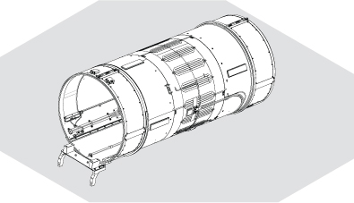
This procedure describes the replacement of the VRMw gradient coil using Gradient Coil Insertion and Lift Kit 2164744-8.
Coolant will be reused after replacement. In case disposal of coolant is required, inform the customer that coolant disposal is needed and then follow the proper customer coolant disposal procedure.
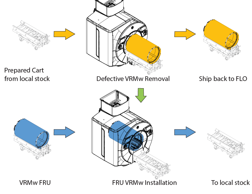
Process flow of VRMw replacement
About this task
| Process | Hrs:Mins | Required person | Days | |||||
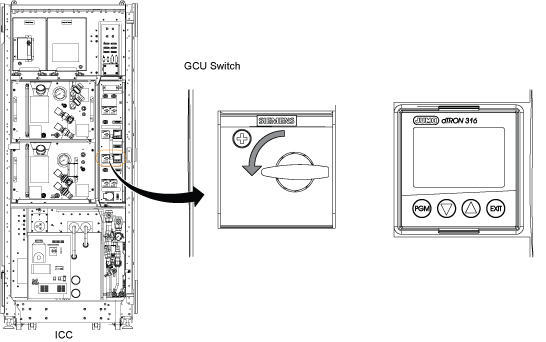
| Power to ISC is turned off and LOTO procedures are implemented. See LOTO for ISC. | 0:10 | 1 | 1st day (12:30) | |||||
|
Undock the detachable patient table and move it outside the scan room. | :01 | 1 | ||||||
| Remove the front endbell. See: Removing the front endbell | :15 | 1 | ||||||
| Remove the rear endbell. See: Removing the rear endbell | 0:15 | 1 | ||||||
| For models with 1-piece bridge, remove the 1-piece bridge. Refer to Removing the 1-piece bridge | :05 | 2 | ||||||
|
Remove the body coil. See RF Body Coil Replacement (See step 5 to step 14 of “4 Procedure”.) Note: Do not remove the front body coil mount since it is used when placing the body coil on the floor as illustration below.
| 1:30 | 3 | ||||||
| STET Tool Setting See Direction Number 5495018. | 1:30 | 2 | ||||||
| Remove all passive shim trays from the VRMw coil prior to the installation and store them in a safe place. See Direction Number 5495018. Passive shim trays are highly ferrous. Heed all warnings in Safety section above. | 1:30 | 2 | ||||||
| Remove STET See Direction Number 5495018. | 0:30 | 3 | ||||||
| VRMw replacement (Remove) | 3:30 | 3 | ||||||
| VRMw replacement (Install) From Preparation before installing VRMw to VRMw gradient coil installation. | 2:30 | 3 | ||||||
See Direction Number 5495018. WARNING: Passive shim trays are highly ferrous. Heed all warnings in Safety section above. | 5:00 | 2 | 2nd day (11:00) | |||||
| 2:30 | 3 | ||||||
|
Add coolant to GCU.
| 0:30 | 1 | ||||||
| :15 | 2 | ||||||
| Return the patient table to the scan room and dock the patient table. Remove LOTO at the ISC. | :05 | 1 | ||||||
|
Do Body Coil Tuning. | 1:00 | 1 | 3rd day (14:20) | |||||
| 0:30 | 1 | |||||||
|
Do a coherent noise test. | 1:00 | 1 | ||||||
|
Do Auto DQA Cal. See DQA II Tool and Troubleshooting | 0:30 | 1 | ||||||
| 0:15 | 1 | |||||||
| 1:00 | 1 | |||||||
|
Do Auto DQA cal (Final). See DQA II Tool and Troubleshooting | 0:30 | 1 | ||||||
| 0:15 | 1 | |||||||
| 1:00 | 1 | |||||||
| Do LV Shim (Grad Shim) | 0:30 | 1 | ||||||
| Wait for 2 hours Before starting B0 drift functional check. | 2:00 | 0 | ||||||
| 1:00 | 1 | |||||||
| 0:30 | 1 | |||||||
|
Do the following tests.
| 1:30 | 1 | ||||||
| 0:40 | 1 | |||||||
| Do a SaveINFO to capture new calibration values. | 0:25 | 1 | ||||||
Coolant water removal
Procedure
- Note: Wear nitrile gloves and safety glasses when removing coolant.Turn off the valve in coolant supply line at the service end of the magnet.
Figure 1. Turn off the valve 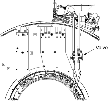
Disconnect the supply and return hose for the gradient coil from the manifold valve assembly.Notice 
- Drain fluid into Tank from return hose.
Figure 2. Draining manifold coolant 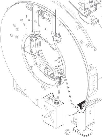
Cable removal and busbar disconnection
Procedure
- At the service end, remove the safety covers from the end of the Y and XZ busbar cable connections.
Figure 3. Y and XZ busbar cables (service end) 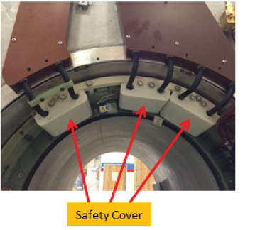
- Note: DO NOT remove the clamps on the busbar leads.Remove the cable clamps.
Figure 4. Clamp locations 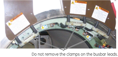
Figure 5. Cable clamps 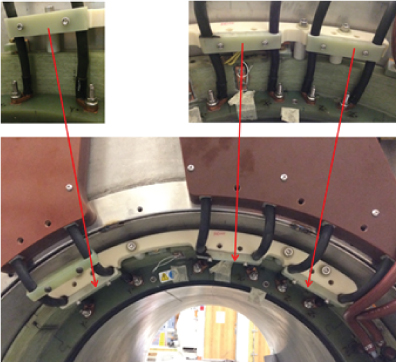
- Remove six M10 nuts and Nord-Lock washers that are securing the busbar lugs to the coil. Slide the busbar terminal lugs off from the studs on the coil. Discard the Nord-Lock washers because they will not be reused. Note:
Never use the nonmagnetic torque wrench to loosen connections, the torque wrench has a range of 10 - 50 N*m ( 8 – 35lbf*ft), removing Nord-Lock© or Spiralock© threads may exceed the limit of this wrench and destroy the ratchet components.
Figure 6. Y and XZ busbar cable connections 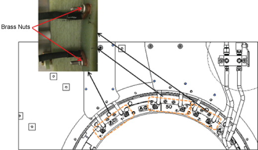
- Unscrew the five screws with washers from the XZ busbar assembly. Note: This procedure is necessary when installing the tube support plate.
Figure 7. XZ busbar assembly 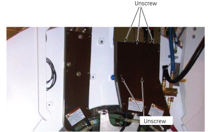
- Remove the interface bracket from the gradient coil.
Figure 8. Interface bracket 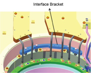
- Remove the four interface bracket studs for interface bracket from the gradient coil.
Figure 9. Interface bracket studs 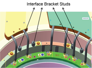
Cable removal
About this task
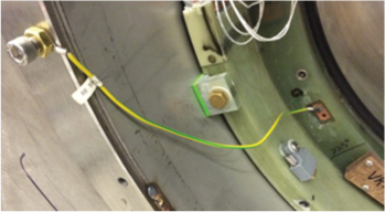
Remove the gradient coil ground cable.
VRMw gradient coil removal
Procedure
- Attach three adapter plates (5338222) to the gradient coil patient end at 3, 9, and 12 o'clock positions with M10 x 20mm bolts. (See Figure 11 and Figure 13.) Attach one M10 nut to the bolts as shown in Figure 12.
Figure 11. Adapter plate on gradient coil - patient end 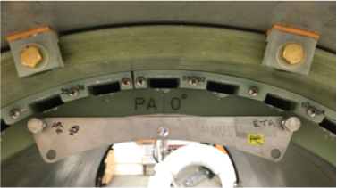
Figure 12. Bolt with nut installed 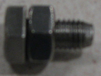
- Attach two adapter plates (5338223) to the gradient coil service end at the 3 and 9 o'clock positions with M10 x 20mm bolts as shown in Figure 13. Attach one M10 nut to the bolts as shown in Figure 12.
Figure 13. Adapter plates on gradient coil - service end 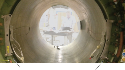
- Obtain the two tube guide roller assemblies (5308402) and mounting plates (5161983, 5161985) from the gradient coil insertion and lift kit shipping crate. Make sure the tube guide roller assemblies are tightly attached to the VRMw mounting plates.
Figure 14. Roller assembly and mounting plates 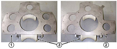
Item Description 1 Mounting Plate, Patient End 2 Mounting Plate, Service End 3 Roller Assemblies
Align the mounting holes of the patient end mounting plate (5161985), including guide roller assembly, with adapter plates (5338222), which are already attached to the gradient coil. Secure installation plate to the adapter plates using M10 x 20mm bolts and M10 nuts.Notice Figure 15. Mounting plate with roller assemblies - patient end 
- Align the mounting holes of the service end mounting plate (5161983), including guide roller assembly, with adapter plates (5338223 and 5338224), which are already attached to the gradient coil. Secure installation plate to the adapter plates using M10 x 20mm bolts and M10 nuts.
Figure 16. Mounting plate with roller assemblies - service end 
- Remove two axial stops from rear end.
Figure 17. Removing the rear axial stop 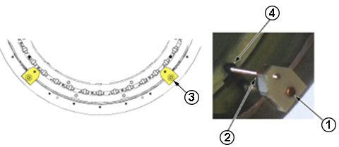
1 M10 x 30 mm Bolt, Brass 2 M10 Nut, Brass 3 Rear Axial Stop 4 Stud on Axial Stop - Remove the two lower standoffs from the tube support plate.
Figure 18. Lower standoffs of tube support plate 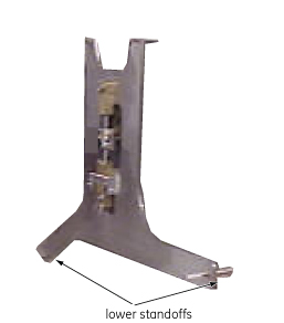
- Attach the Wing Adapters (5339882, Item 2) to the tube support plate with stainless steel 0.75 in. 16 x 1.25 in. long bolts.
Figure 19. Support plate with wing adapters 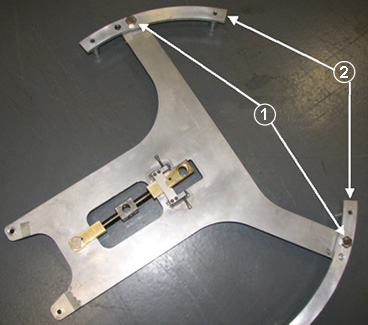
- Before installing the tube support plate, remove the rear service end wedges at the 1 and 2 locations.
Figure 20. Systems with 10 wedges: Axial stops and wedges 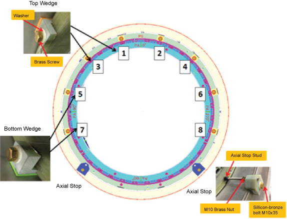
- Attach the tube support plate to the magnet service end by inserting the 100 mm M10 x 25 stainless steel studs (5303994) 3/8 in. (13 mm) into the magnet, and secure them with the stainless steel washers and M10 nuts from the Gradient Coil Insertion and Lift Kit.
Figure 21. Support plate attached on the interface ring 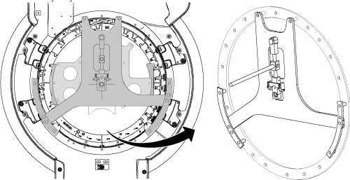
Moving VRMw with cart
Procedure
Warning 
Place tube jack assembly (5191132) in the cart. Make sure the back of the jack assembly fits properly into the cart.Notice Figure 22. Jack assembly placement 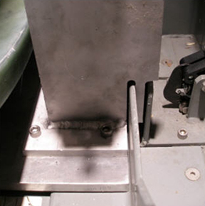
- Maneuver the cart to the patient end of the magnet, and position it in front of the magnet with at least a 2 in. (50.8 mm) gap between the cart and the magnet interface ring (required for lower wedge removal.)
Figure 23. 2-inch gap between the magnet and cart 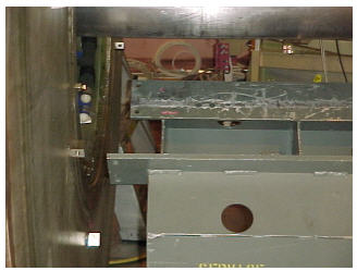
- Retrieve the male Insertion Tube (2284929) and Tube Standoff (5191626).
- Attach the tube standoff to the male insertion tube using the 4 inch, 0.375-16 UNC hex socket screw (5303993) included in the gradient coil insertion and lift kit.
- After the standoff is secured to the tube, attach the tube pilot shaft to the standoff.
Figure 24. Attaching the standoff to the insertion tube 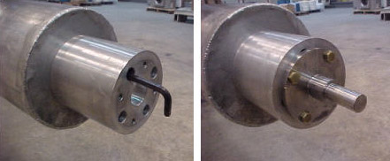
- Remove the PVC shield from the brass thread of the male insertion tube.
Figure 25. PVC shield for brass thread 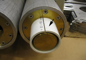
- Slide the male insertion tube through the tube guide roller assemblies at both sides of the Gradient Coil, push the pilot shaft through the support plate mounting bearing, and insert a nonmagnetic safety pin through the hole in the pilot shaft.
Figure 26. Tube pilot shaft and support plate 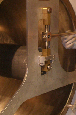
With one person holding the male insertion tube to keep it from rolling, two people should obtain the female insertion tube from the shipping crate and thread the two tubes together.Notice Note: Each of the two pieces of the gradient insertion tool weighs less than 35lb (15.9kg).Figure 27. Setting up insertion tube assembly 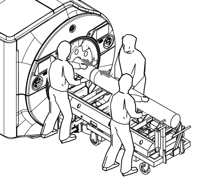
Recheck the centering of the cart left-to-right with respect to the magnet bore, and adjust the longitudinal alignment of the cart if required.Notice - Simultaneously raise the tube jack and the support plate mounting bearing to lift the Gradient Coil.
Figure 28. Raising VRMw gradient coil 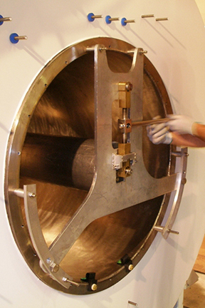
Properly secure gradient coil to coil cart with Shipping Brackets (5357473).CAUTION Figure 29. Shipping brackets (example at one location) 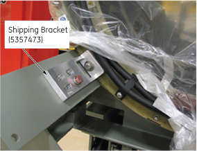
Remove the insertion tool from the Gradient Coil per following steps.CAUTION - Remove safety pin from the support plate.
Figure 30. 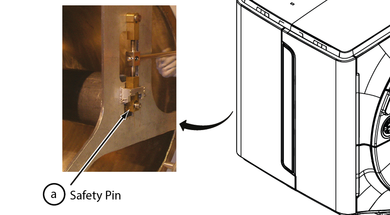
Note: Each of the two pieces of the gradient insertion tool weighs less than 35lb (15.9kg).Figure 31. Removal of tool 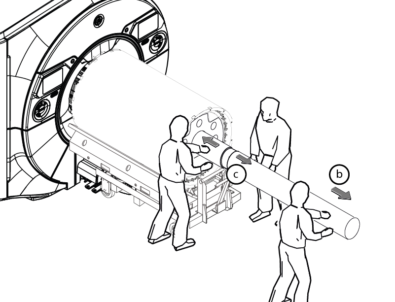
- Remove safety pin from the support plate.
- Remove the mounting plates from the Gradient Coil.
Figure 32. Mounting plates removal 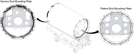
Preparation before installing VRMw
Procedure
- Attach three adapter plates (5338222) to the Gradient Coil patient end at 3, 9, and 12 o'clock positions with M10 x 20mm bolts. (See Figure 33 and Figure 35.) Attach one M10 nut to the bolts as shown in Figure 34.
Figure 33. Adapter plate on the gradient coil - patient end Figure 34. Bolt with the nut installed - Attach two adapter plates (5338223) to the Gradient Coil service end at the 3 and 9 o'clock positions with M10 x 20mm bolts. (See Figure 35.) Attach one M10 nut to the bolts as shown in Figure 34.
Figure 35. Adapter plates on the gradient coil - service end - Remove the shipping brackets that are securing the Gradient Coil to the cart.
Figure 36. VRMw shipping bracket 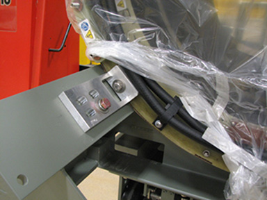
- Remove the Gradient Coil cradle fasteners, two per side, from the cradle.
Figure 37. Removing cradle fasteners 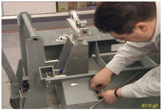
- Obtain the two tube guide roller assemblies (5308402) and mounting plates (5161983, 5161985) from the Gradient Coil insertion and lift kit shipping crate. Make sure the tube guide roller assemblies are attached to the mounting plates.
Figure 38. Roller assembly and mounting plates Item Description 1 Mounting Plate, Patient End 2 Mounting Plate, Service End 3 Roller Assemblies
Align the mounting holes of the patient end mounting plate (5161985), including guide roller assembly, with adapter plates (5338222), which are already attached to the gradient coil. Secure installation plate to the adapter plates using M10 x 20mm bolts and M10 nuts.Notice Figure 39. Mounting plate with roller assemblies - patient end 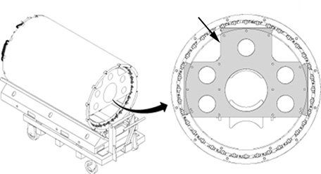
- Align the mounting holes of the service end mounting plate (5161983), including guide roller assembly, with adapter plates (5338223 and 5338224), which are already attached to the Gradient Coil. Secure installation plate to the adapter plates using M10 x 20mm bolts and M10 nuts.
Figure 40. Mounting plate with roller assemblies - service end 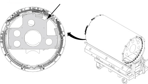
- Obtain the male insertion tube (2284929) and tube standoff (5191626).
- Attach the tube standoff to the male insertion tube using the four-inch, 0.375-16UNC hex socket screw (5303993) included in the Gradient Coil insertion and lift kit.
- After the standoff is secured to the tube, attach the tube pilot shaft to the standoff.
Figure 41. Attaching the standoff to the insertion tube - Remove the PVC shield from the brass thread of the male insertion tube.
Figure 42. PVC shield for brass thread
VRMw gradient coil installation
Procedure
- Obtain tube support plate assembly 2284928-2 from the Gradient Coil insertion and lift kit shipping crate.
- Make sure the two Wing Adapters (5339882) are attached with 0.75 inch, 16 x 1.25 in. long stainless steel bolts (1).
- Secure the tube support plate assembly and wing adapters to the magnet flange at the service end with M10 studs, spacers, and M10 nuts (2).
Figure 43. Attaching the tube support plate 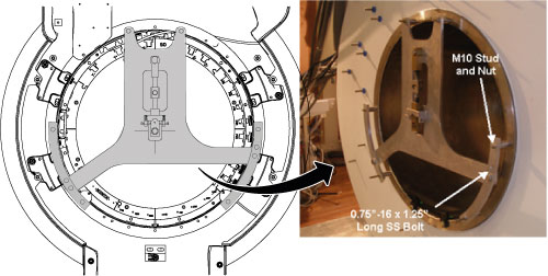
- Adjust the tube support plate assembly's horizontal adjustment screws until the tube support bearing is centered left-to-right.
Figure 44. Adjusting the support plate 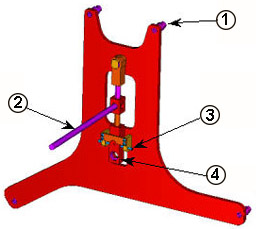
1 Spacer 2 Vertical Adjustment Lever 3 Horizontal Adjustment Screw 4 Support Bearing
Place the tube jack assembly (5191132) in the cart. Make sure the back of the jack assembly fits properly into the cart.Warning Figure 45. Jack assembly placement - Maneuver the cart and gradient coil to the patient end of the magnet, and position it in front of the magnet with at least a 2 in. (50.8 mm) gap between the cart and the magnet interface ring (required for lower wedge removal)
Figure 46. 2-inch gap between the cart and magnet - Raise or lower the cradle of the cart as required to vertically align the tube support plate at the magnet and the gradient mounting plates at the Gradient Coil.
Figure 47. Adjusting the height of the cart 
With one person holding the male insertion tube to keep it from rolling, two people should obtain the female insertion tube from the shipping crate and thread the two tubes together.Notice Figure 48. Setting up the insertion tube assembly 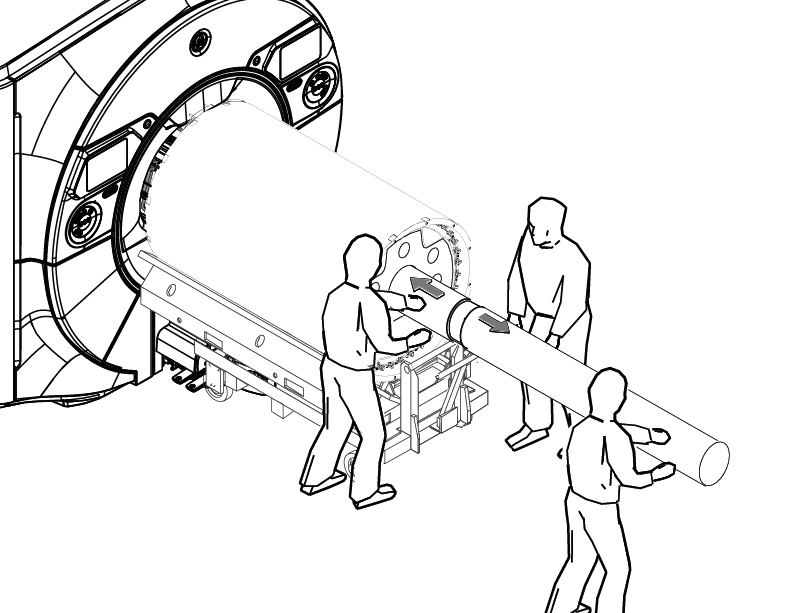
Push the complete insertion tube assembly into the magnet bore. Get the tube pilot shaft as close to (but not touching) the tube support plate as possible.Notice Figure 49. Complete the insertion tube assembly 
- Push the pilot shaft through the support plate mounting bearing. Insert a nonmagnetic safety pin through the hole in the pilot shaft.
Figure 50. Tube pilot shaft and support plate - Raise the tube jack and support plate mounting bearing to lift the gradient coil up. Keep the coil approximately level with the magnet bore during the lifting. The coil should be able to rotate freely when completely lifted off the cart.
Figure 51. Raising the gradient coil - At the magnet patient end, attach the gradient alignment T-block and the gradient coil radial alignment tool as follows.
- Mount the gradient alignment T-block (5389303) to the gradient coil patient end, using two M10x25 SS FHSCS (5389090-3) at –15deg and +15deg hole in the coil’s flange.
- Mount the gradient alignment tool (5266402) to the magnet patient end, using 2 M10x25 SS bolts (46-318508P20) at –15deg and +15deg hole in the magnet interface ring.
Figure 52. Gradient alignment tools 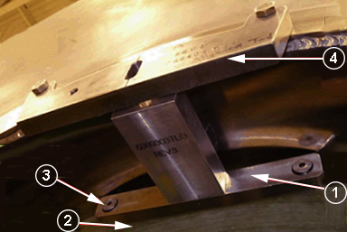
- Carefully roll the gradient coil and stop the coil when the T-block (5389303) starts to make contact with the alignment tool (5266408).
Figure 53. Aligning gradient coil (front-to-back) 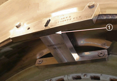
- Align the coil clocking direction as follows.
- Roll the gradient into position until the center hole of the alignment T-block (5389303) aligns with the slot of the alignment tool (5266408) on the magnet.
- Place the thumbscrew (part of the gradient alignment tool) though the slot and thread it into the alignment T-block on the coil. Engage the rotational locks on the carriage assembly to hold the position.
Figure 54. Aligning the gradient coil (clocking) 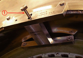
- Make sure the gradient axial and radial alignment has not changed. Install the pad under the coil as following step.
- Carefully position the end of the blanket that is taped under the rear end of the gradient ensuring that the blanket is flat on the inside surface of the bore.
Figure 55. Position the blanket 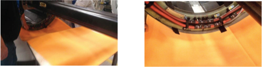
- The blanket should be even with the gradient, approximately 110 +/- 10 mm from each end of the bore.
Figure 56. Pull the blanket 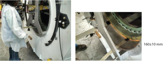
- Carefully position the end of the blanket that is taped under the rear end of the gradient ensuring that the blanket is flat on the inside surface of the bore.
- Re-install the Axial Stop Assembly for patient at the patient end of the magnet. Make sure that the Gradient Coil is making contact with the patient end axial stops. Slowly lower the Gradient Coil onto the pads. Release pressure on the beam, so that the coil is supported by the mounting pads.
Figure 57. Lowering the gradient coil with the radial alignment tool 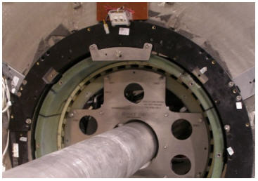
- Tighten the axial stop stud towards the Gradient Coil to a torque of 10~12 ft-lbs. In presence of magnetic field, use hand-tight (until resistance felt) plus 1 full turn with a non-ferrous screwdriver. Tighten the M10 brass nut on the coil side of the axial stop bracket to 10~12 ft-lbs. In presence of magnetic field, use hand-tight (until resistance felt) plus 1/2-turn.
Figure 58. Axial stop Item Description 1 M10 x 30 mm Bolt, Brass 2 M10 Nut, Brass 3 Rear Axial Stop 4 Stud on Axial Stop - Install the four bottom wedges (5566941) (with one M10 x 24 mm washer and one brass M10 x 35 mm hex head bolt per wedge) on the patient end of the magnet flange in the order shown in Figure 59 from 5 to 8.
Figure 59. Installation sequence of stops and wedges After the wedge is fitted firmly into the slot, secure it to the gradient coil flange using one G10 washer (5146169) and one brass hex head M10 x 35 screw (5110638-65) with Loctite 263 or 271.
-
Loctite 263 or 271 should be applied to the engagement portion of the brass bolt.
-
Do not drive the wedge to contact the gradient coil structure.
-
There should be a gap between the wedges and the gradient coil flange after tightening all the bolts.
-
If a bolt appears to be bottomed out earlier, use a second G10 washer (5146169).
-
Do not use more than two (2) washers on any one location.
Tighten the brass bolts (in the same order, pair-by-pair, as the wedges were installed) securely to the stops and wedges.
-
Notice Note: Observe the following:Re-install busbar cables to new gradient coil. Place a new Nord-Lock washer over each stud.-
Always use the new Nord-Lock washers that come with the FRU package. DO NOT reuse the old Nord-Lock washers.
-
Nord-Lock washers consist of two pieces, which are generally glued together. Always use a complete set with two pieces joined together in correct orientation. DO NOT use a separated single piece.
Figure 60. Nord-Lock washers 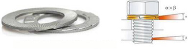
After putting the cable connection on the stud, place a new Nord-Lock washer over each stud.
Put two drops of Loctite 243 on the exposed thread. (Shake the bottle first.)
Do not get Loctite on the Nord-Lock washer.
Hand-tighten the nut.
Discard the old washers.
Installation Sequence:
-
Power cable lug
-
Nord-Lock washer
-
Brass nut
Figure 61. Loctite on the stud 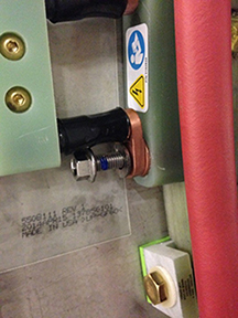
Figure 62. Installation of the busbar cables to the new gradient coil -
DANGER Notice Notice
Set the torque wrench to 25 ft-lbs or 33.9 Nm. Install 15 mm socket on the extension.Notice  Note: Make sure that the arrow on the torque wrench is visible. If the arrow is not visible, the torque wrench will not “click” when the proper torque is reached.
Figure 63. Arrow on Non-magnetic torque wrench 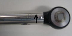
- Using a Sharpie pen, place a line from the base of the stud to the nut.
Figure 64. Stud and the nut marked to show torque position 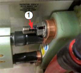
Item Description 1 Black line on the nut and stud to show torque position. - Reinstall the safety covers over the cable.
Figure 65. Y and XZ busbar cables (service end) - Open the coolant valve at the rear of the magnet.
Figure 66. Hose connections for gradient return and supply 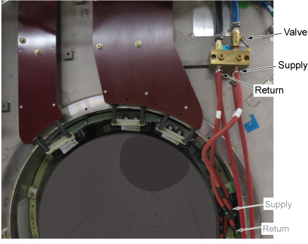
Finalization
Procedure
- Return the VRMw with the cart (originally stored in local stock) as it was shipped and restore the cart (originally shipped with FRU) to the local stock.
Figure 67. VRMw cart operation