Prerequisites
Table 1. Personnel requirements| Required persons | Preliminary requirements | Procedure | Finalization |
|---|
| 1 | Not Applicable | 30 minutes | 15 minutes |
Table 2. Tools and test equipment| Item | Quantity | Effectivity | Part number | Manufacturer |
|---|
| Standard Tool | 1 | - | - | - |
Table 3. Replacement parts| Item | Quantity | Effectivity | Part number | Manufacturer |
|---|
| DCPS for Driver Module | 1 | - |
Refer to FRU Manual
| - |
Table 4. Safety
| Warning |
|---|
| ELECTROCUTION HAZARD! Dangerous and or fatal voltages are present in the energized cabinet. Follow LOTO steps as given in first section of this document to disable and verify safe voltage levels. |
|
About this task
Location of each DC Power Supply is as following illustration
Figure 1. Location of DC Power Supply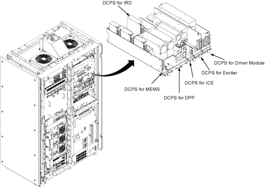
Procedure
- Open ISC Covers.
- Remove DCPS cable bracket.
- Loosen two screw.
- Rotate up a little at right side and remove the bracket.
Figure 2. DCPS cable bracket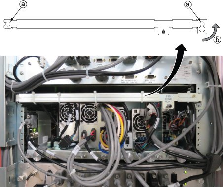
- Disconnect the following cable connectors.
| Notice |
|---|
 | DCPS Tray is tightly inserted in the bracket. Need enough pull force to remove it. |
Remove the DCPS for Driver Module tray from ISC.- Loosen 2 screws tightening power supply and chassis.
- Slide out the tray.
Figure 3. Driver Module power supply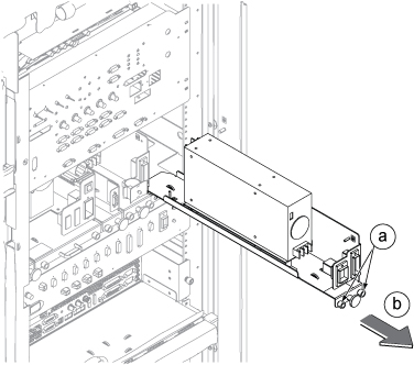
- Restore new DCPS for Driver Module tray by the reverse order of removal.
- Restore the ISC by the reverse order of the removal.
Finalization
- Restore the Power. Refer to Removing LOTO - ISC.
- Perform Check scan.
