
- SIGNA™ Hero 3.0T Service Methods
- 5852800-8EN Revision 1.0
- 00000018WIA308DB230GYZ
- id_156675441.9
- Jul 13, 2021 4:27:36 PM
GCU Replacement
Prerequisites
| Required persons | Preliminary requirements | Procedure | Finalization |
|---|---|---|---|
| 1 | Not Applicable | 90 minutes | 15 minutes |
| Item | Quantity | Effectivity | Part number | Manufacturer |
|---|---|---|---|---|
| Standard Tool | 1 | - | - | - |
| 20L Draining Tank | 3 | - | - | - |
| Water Hand Pump | 1 | - | - | - |
| 150MM FUNNEL | 1 | - | - | - |
| Hoist Service Kit | - | - |
5196226 | - |
| Flexible Water Tank (In System) | 1 | - |
5342981 | - |
| Item | Quantity | Effectivity | Part number | Manufacturer |
|---|---|---|---|---|
| Towels | NA | - | - | - |
| Item | Quantity | Effectivity | Part number | Manufacturer |
|---|---|---|---|---|
| GCU | 1 | - |
Refer to FRU Manual | - |
| ||||
| Condition | Reference | Effectivity |
|---|---|---|
|
ICC facility water valve will be turned off. Check the hospital facility chiller valve integrity to avoid the excessive loads on the facility water pumps and lines. | - | - |
|
ISC Power must be turned OFF. Refer to Lockout / Tagout for ISC. | - | - |
Procedure
- Release the bands from the shipping base, flip the slide plate, and slide the FRU Box.
Figure 1. Slide GCU FRU Box 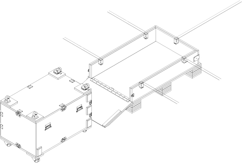
- Open GCU FRU Box, turn the top cover upside down.
Figure 2. Open GCU FRU Box 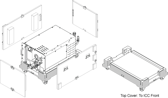
- Open ICC Cover and remove it.
Figure 3. Remove cover 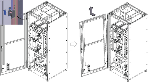
- Confirm that ISC power is off and LOTO is performed. Then, check the followings.
- GCU/CCU pressure meter (black meter) is at zero.
- ICC Control Unit TCU display is OFF.
Figure 4. Confirmation 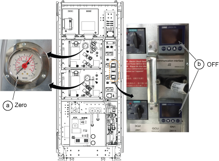
- Turn off the F50 Power.
- Turn off the “Drive Switch”.
- Turn off the “Main Power Switch”.
Figure 5. F50 Power OFF 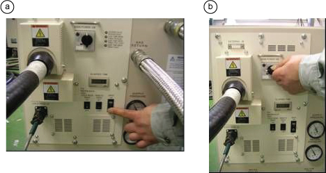
Turn OFF the supply and return valves for Facility Water in FPU.Notice Figure 6. Turn off valves for facility water 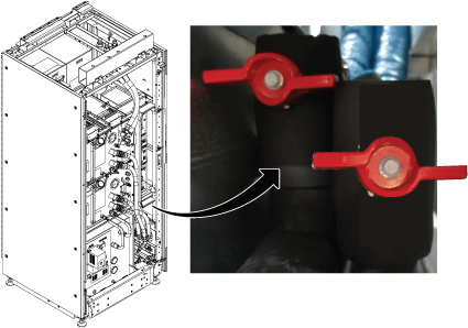
- Drain the supply water to release the water pressure per following steps.
- Connect the hose to drain port of water supply.
- Insert the other side of hose into the flexible tank.
- Open valve and check that the pressure meter becomes zero.
- Close the valve and remove the hose.
Figure 7. Drain the supply water 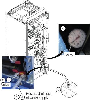
- Drain the coolant in GCU Tank.
- Unscrew the cap from the GCU tank.
- Prepare two 20L Draining Tanks and draining hose with L connector.
- Insert L connector to the tank draining nipple. The valve inside will open auto-matically by connecting the mating connector and draining will start.
- When the coolant fills Tank to half full (about 4 minutes), remove the L connector once and replace the Tank. Then, connect the L connector to nipple to restart the draining.
- Wait until the draining stops from the hose. (Total time about 10 minutes for two tanks).
Figure 8. Draining for the Tank 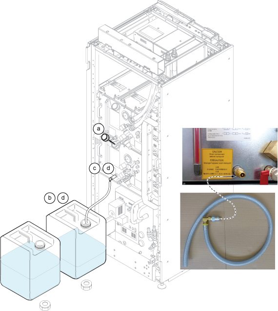
- Drain the coolant in GCU Pump.
- Prepare 20L Draining Tank and draining hose with coupling nut.
- Connect the hose connector to the pump draining nipple.
- Open the valve and draining will start.
- Wait until the draining stops from the hose. (Minimal coolant in the pump.)
- Close the valve which is opened in step c.
Figure 9. Draining for the Pump 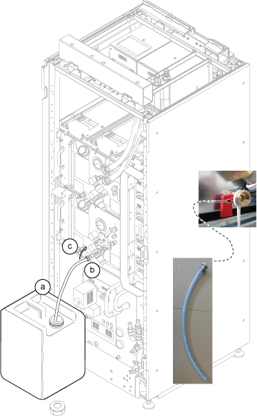
- Loosen screws around the ICC rear cover and remove the ICC rear cover by lifting up a little.Note: If there is any difficulty to remove the cover, remove screws.
Figure 10. ICC Rear Cover removal 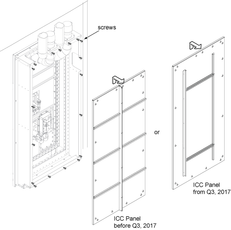
At Scan Room, fold and bind each GCU hoses using tie wrap to prevent from draining.Notice 
Figure 11. Fold hoses 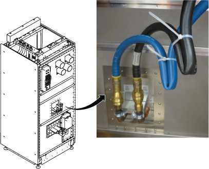
- Hold the towel by one hand under the hose and disconnect hose connectors of GCU. Then, connect the hoses together until you hear the click sound.
Figure 12. GCU Hoses at pen panel 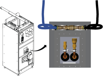 Note: Here is the tips how to connect the quick disconnect for VRMw.
-
Pull the coupler grip.
-
Insert the male connector.
-
Push both connectors together until you hear the click sound.
Figure 13. Quick Disconnect tips 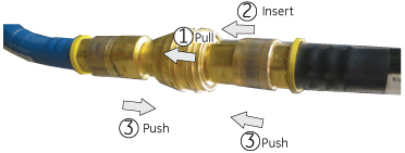
-
- Disconnect the Blue Quick Disconnect hoses for GCU and CCU.Note: CCU connectors are removed since they prevent the GCU from being slid out.Note: When disconnecting the Blue Quick Disconnect hoses, disconnect quickly to avoid excessive spilling of coolant
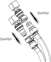
Figure 14. Quick Disconnect Hoses 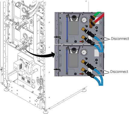
- Disconnect 2X1 and 2X11 Cables from Control Unit.
Figure 15. Cables at Control Unit 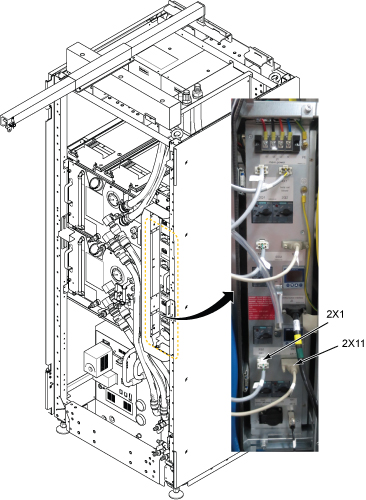
- Setup Hoist. Refer to Hoist Setup.
Figure 16. Setup Hoist 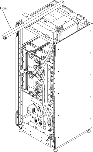
- Loosen four screws and carefully withdraw GCU from the chassis.Note: Before withdrawing the GCU, lift up the stopper.
Figure 17. Stopper 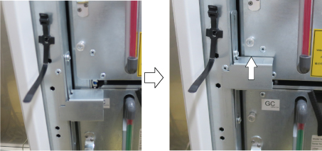
Figure 18. Withdraw GCU 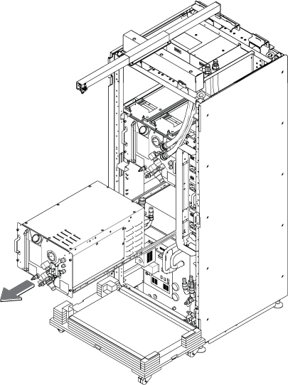
- Attach the lifting brackets to both sides of the GCU. The lifting brackets can be found in the GCU FRU crate.
Figure 19. Lifting Brackets 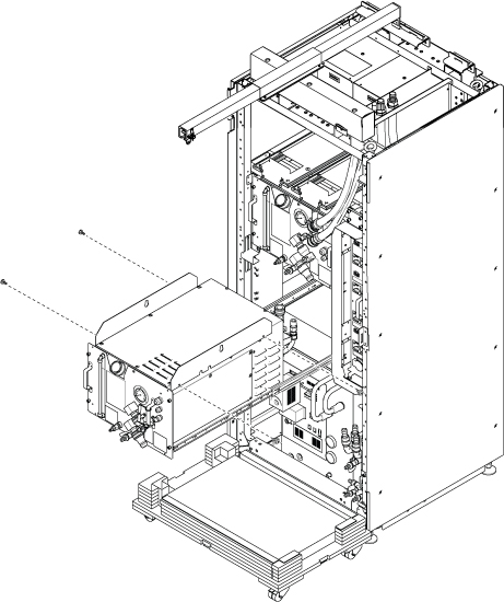
- Note: Make sure the hook is seated in the lifting bracket. If not, the weight can shift causing harm to the equipment or engineer.Ratchet the winch to tighten the chain.
Figure 20. Ratchet 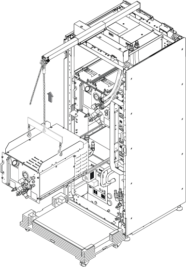
- Push the rail slider into the cabinet before lowering GCU.
Figure 21. Push Rails 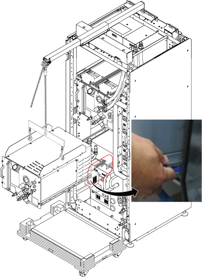
- Use the hoist and slowly lower the GCU Chassis to the top FRU Box.
Figure 22. Lower GCU 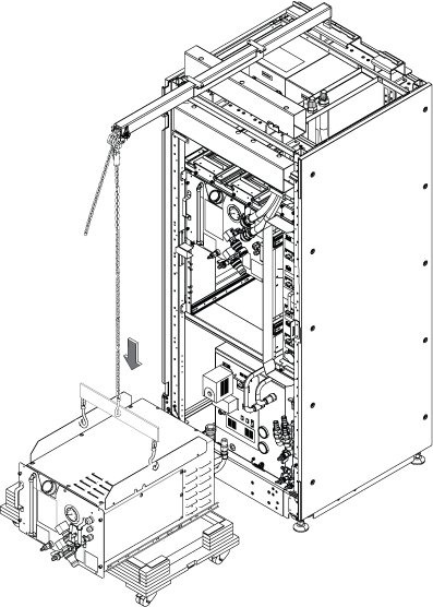
- Remove the slide rails from GCU.
Figure 23. Remove slide rails 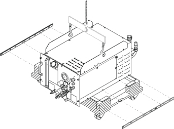
- Slightly lift up the GCU, rotate the FRU top cover by 90 degree, and lower the GCU into the FRU Box.
Figure 24. GCU into the FRU Box 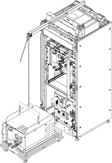
Restore the GCU by reverse order of removal.CAUTION 
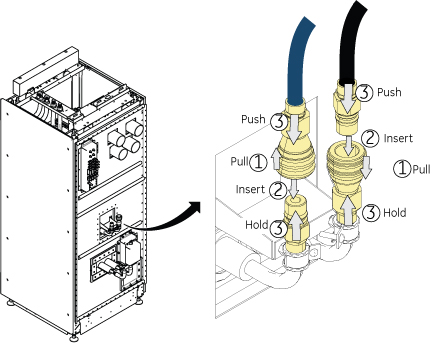
- Restore all hoses.Note: Hold the towel under the hose when restoring the hoses.Note: Do not forget to restore the VRMw Hoses
Figure 25. Restore hoses 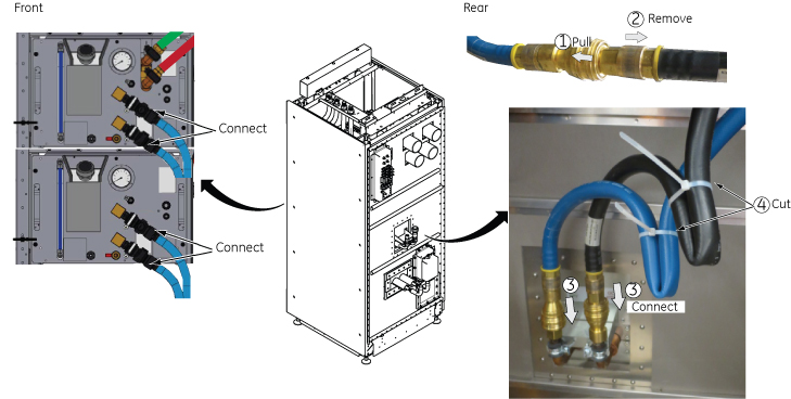 Note: Here is the tips how to connect the quick disconnect for VRMw.
-
Pull the coupler grip.
-
Insert the male connector into the coupler.
-
Push both connectors together until you hear the click sound.
-
- Open valve for Facility water.
Figure 26. Open Valve 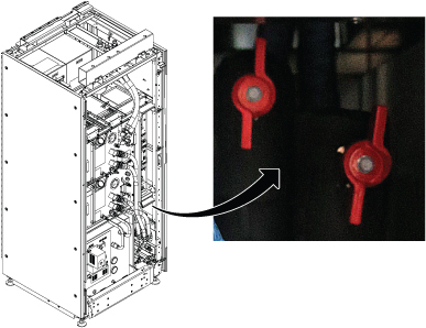
- Transfer the coolant to the other empty tank using funnel about 3~4L (1 gallon or so) for one hand operation.
Figure 27. Transfer Coolant 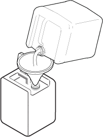
- Turn OFF the following sub breakers at ISC PDU in following order for safe refill operation.
- RF Amp OFF (First rotation of refill only. Skip from second rotation.)
- Gradient OFF (First rotation of refill only. Skip from second rotation.)
- System Cooling OFF.
Figure 28. Turn OFF sub breakers 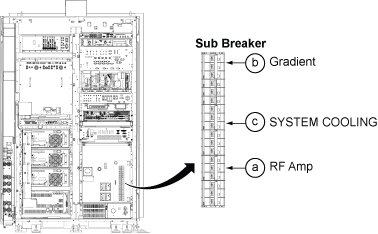
- Refill the coolant per following steps.
Figure 29. Refill 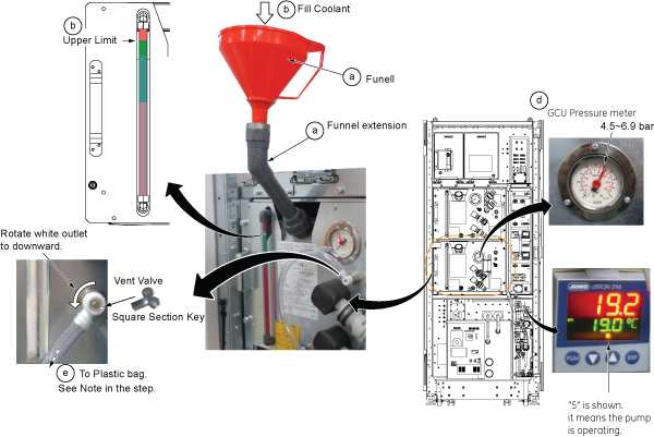
Finalization
- Perform check scan.
- Disassemble the hoist kit and restore it to the stored location.
- Package the FRU Box crate including the defective part and return.