- id_13105872
- Version: 3.5
- Date: Feb 6, 2020 1:58:19 PM
Room ambient and bore temperature sensors replacement
Prerequisites
| Required persons | Preliminary requirements | Procedure | Finalization |
|---|---|---|---|
| 1 person for each sensor replacement procedure | Not Applicable | 5 hours for bore temperature sensor; 1 hour for room ambient temperature sensor | 15 minutes |
| Item | Quantity | Effectivity | Part number | Manufacturer |
|---|---|---|---|---|
| Digital Volt Meter (DVM) | 1 | - | - | - |
| Nonmagnetic Titanium Service Tool Kit, Large Set | 1 | - | 5112581 | - |
| Item | Quantity | Effectivity | Part number | Manufacturer |
|---|---|---|---|---|
| Bore Temperature Cable and Sensor (Run 3350, MAG-SRI-J10 to Mag-Bore, Bore Temp Sensor) | 1 | - |
See FRU Manual |
- |
| Left-Front Arc Cover Assembly (includes Room Ambient Temperature Sensor) | 1 | - |
See FRU Manual |
- |
| Condition | Reference | Effectivity |
|---|---|---|
| Be sure that the left-front arc cover assembly and the bore temperature cable and sensor have all the required contents. | - | - |
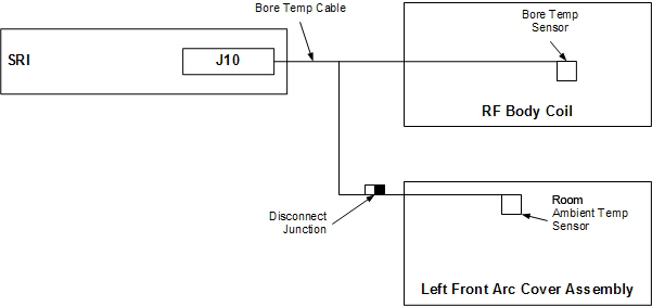
This procedure describes the replacement of the two temperature sensors associated with the magnet. The location of the room ambient temperature sensor depends on the system. The sensor is located in the patient monitoring accessory hook on the left side of the enclosure (see Figure 2). The patient bore temperature sensor is located inside the RF body coil. The bore temperature cable connects to the room ambient temperature sensor, and the patient bore temperature sensor connects to the SRI. The room ambient temperature sensor and cable plug into the bore temperature cable (see Figure 1). When replacing the room ambient temperature sensor, the left-front arc cover assembly must also be replaced, because the sensor is epoxied into the arc cover.
Figure 1. Room ambient and bore temperature sensors
Room ambient temperature sensor replacement
Procedure
- Apply LOTO on the RF amplifier and PEN cabinet. See the MR Service Safety Manual, PN 5452735.
- Remove the side cover and left skirt cover. See Side Cover Removal and Installation and Skirt Cover Removal and Installation.
- Remove the front cover. See Front Cover Removal and Installation.
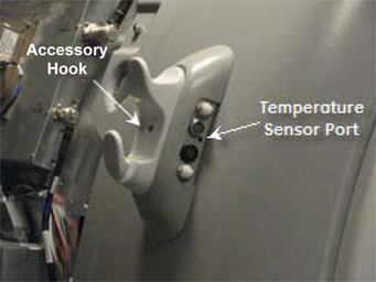
- Disconnect the patient monitoring connectors from the accessory hook.
Figure 2. Accessory hook
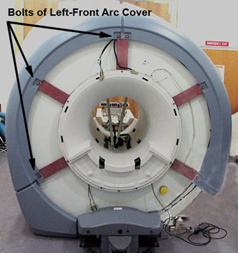
- Remove the left-front arc cover assembly. There are three bolts on the front and one bolt on the side.
Figure 3. Left-Front arc cover assembly
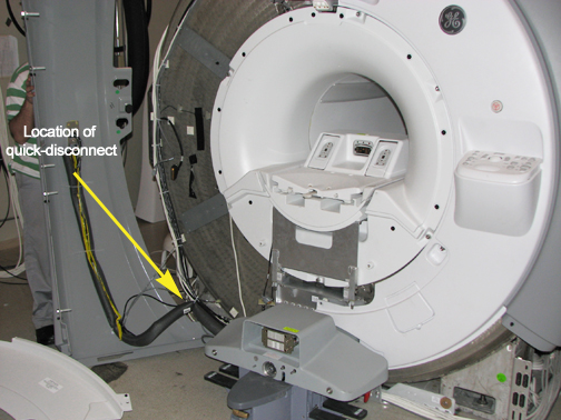
- Disconnect the room ambient temperature sensor from the bore temperature sensor cable. The room ambient temperature sensor cable is approximately 72 inches (180 cm) long and the connector should be near the bottom of the left-front arc cover.
Figure 4. Connector at bottom of Left-Front arc cover
- Disconnect the remaining cables/hoses from the left-front arc cover assembly.
- To install a new room ambient temperature sensor, follow Step 1 through Step 7 (above) in reverse order.
Patient bore temperature sensor replacement
Procedure
- Perform LOTO on the RF amplifier and PEN cabinet. See the MR Service Safety Manual, PN 5452735.
- Remove the left side cover, left skirt cover, and front cover to access the quick disconnect. See Side Cover Removal and Installation, Skirt Cover Removal and Install and Front Cover Removal and Installation.
- Disconnect the bore temperature sensor cable from J10 on the SRI under the left side of the magnet enclosure and pull to the front of the magnet.
- Disconnect the room ambient temperature sensor cable. The room ambient temperature sensor cable is approximately 72 inches (180 cm) long and the connector is near the bottom of the left-front arc cover.
- Remove the split bridge Bridge and Longitudinal Drive Belt Replacement.
- Remove the front end bell Front End Bell Removal and Install.
- note: As long as the rear end bell is in place and the RF body coil is returned to the bore in the same orientation as it was removed, then RF coil tuning will not be affected. It may be necessary to mark the original body coil position.Partially remove the RF body coil RF Body Coil Replacement.
- Carefully remove the tape located under the sensor. Keep the tape to reused it later.
- Pull the sensor from the RF body coil port.
- Remove the bore temperature sensor cable by threading it through the magnetic enclosure.
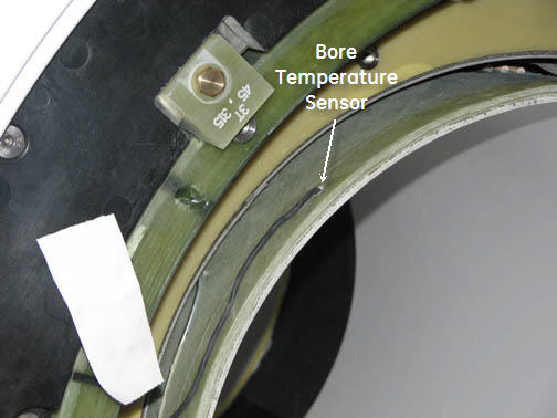
- Route the new cable through the magnet enclosure and tape it
to the RF body coil at the 315 position. Reconnect the bore temperature
sensor cable at J10 on the SRI under the left side of the magnet enclosure,
and reconnect the room ambient temperature sensor cable.
Figure 5. Bore temperature sensor cable
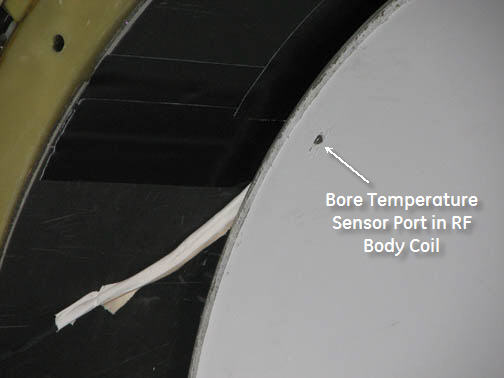
- Insert the bore temperature sensor into the port in the RF body
coil and secure it with tape.
Figure 6. RF body coil port
- Replace the RF body coil, front end bell, split bridge, and covers per Step 1 through Step 7 (above) in reverse order. Take care to not pinch the cable.
Finalization
Finalization
- Remove LOTO from the PEN cabinet. See the MR Service Safety Manual, PN 5452735.
- Perform a quick head and body scan to ensure that the system is functioning properly.