- id_12373665
- Version: 1.8
- Date: Dec 16, 2019 2:21:27 PM
Body Hybrid Replacement
Prerequisites
| Required persons | Preliminary requirements | Procedure | Finalization |
|---|---|---|---|
| 2 for MR750; 1 for MR450, MR450w, MR450w GEM | Not Applicable | 30 minutes | 30 minutes |
| Item | Quantity | Effectivity | Part number | Manufacturer |
|---|---|---|---|---|
| Non-Magnetic Service Tool Kit | 1 | - |
5112581 |
- |
| Item | Quantity | Effectivity | Part number | Manufacturer |
|---|---|---|---|---|
| 1.5T Body Hybrid Module | 1 | - |
See FRU Manual |
- |
|
Removing Body Hybrid Splitter
Procedure
- Perform LOTO on the PDM-RF power for the system. See the MR Service Safety Manual, PN 5452735.
- Make sure the scanner is idle. Select End Exam at any point in the scan process.
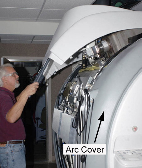
- Remove the lower side cover and upper magnet side cover to access
the body hybrid module.
Figure 1. Removing Upper Magnet Side Cover
- Remove all connections to the body hybrid assembly.
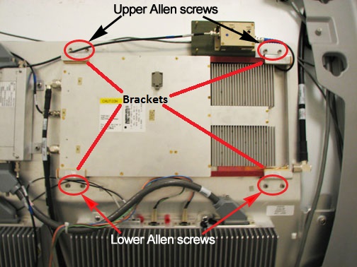
- Loosen the 4 screws on the bottom clamp brackets that secure
the body hybrid to the magnet. Remove the 4 screws and 2 clamp brackets
that secure the top of the body hybrid to the magnet.
Figure 2. 1.5T Body Hybrid Module
 caution
- Remove the module from the magnet room, and keep it as far away from the magnet as possible.
Installing Body Hybrid Module
Procedure
- caution
- Move the module into the magnet room, and keep it as far away from the magnet as possible.
- Reconnect all cables to the body hybrid.
- Slide the body hybrid into position using the lower clamp brackets. Reinstall the upper clamp brackets with the 4 screws. Secure the module to the magnet by tightening all 8 screws. See Figure 2.
- Replace all covers in reverse order.
- Remove LOTO and reapply power to the system. See the latest revision of the MR Service Safety Manual, PN 5452735.
Finalization
Procedure
- Perform a TR Dynamic Disable Calibration.
- Perform System gain calibration.
- Complete a body and head scan to make sure the system is functional (see Check Scan).