- id_13105928
- Version: 3.11
- Date: Feb 12, 2020 9:31:19 AM
RF body coil replacement
Prerequisites
| Required persons | Preliminary requirements | Procedure | Finalization |
|---|---|---|---|
| 2 minimum | Not Applicable | 240 minutes | 40 minutes |
| Item | Quantity | Effectivity | Part number | Manufacturer |
|---|---|---|---|---|
| Small Carpenter’s Level | 1 | - | - | - |
| Field RF Coil Tuning Kit | 1 | - |
5311727 |
- |
| Nonmagnetic Titanium Service Tool Kit, Large Set | 1 | - | 5112581 | - |
| Item | Quantity | Effectivity | Part number | Manufacturer |
|---|---|---|---|---|
| Adhesive | 1 | - |
46-220312P1 |
- |
| Anti-Seize | 1 | - |
2119594 |
- |
| Item | Quantity | Effectivity | Part number | Manufacturer |
|---|---|---|---|---|
| Discovery MR450 1.5T Body Coil and FRU Case | 1 | - |
See FRU Manual. |
- |
|

| Condition | Reference | Effectivity |
|---|---|---|
| Contact a trained, local body coil tuning expert before starting this procedure, because the coil will need to be tuned as part of the replacement finalization. If necessary, contact the Modality Operations Manager for a list of trained individuals. | - | - |
Use this procedure to replace the RF body coil.
Remove RF body coil
Procedure
- Perform LOTO on the PDU/gradient subsystems, XRFD amplifier, and PEN cabinet. See MR Service Safety Manual, PN 5452735.
- Remove the split bridge. See Bridge and Longitudinal Drive Belt Replacement.
- Remove the front end bell. See Front End Bell Removal and Installation.
- Disconnect the four DD bias lines in the front, and the I and Q lines in the rear of the RF body coil.
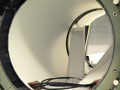
- Disconnect the bore lights from the RF body coil. Pop out the four pop pins before removing the bore lights.
Figure 1. Bore lights
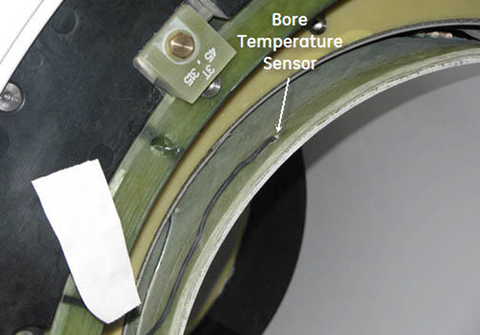
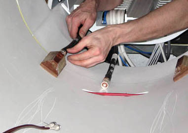
- notice: Do not use the air hose manifolds to remove the RF body coil.Partially slide out the old RF body coil, and disconnect the bore temperature sensor and tape it to the magnet enclosure so it is out of the way.
Figure 2. Bore temperature sensor cable
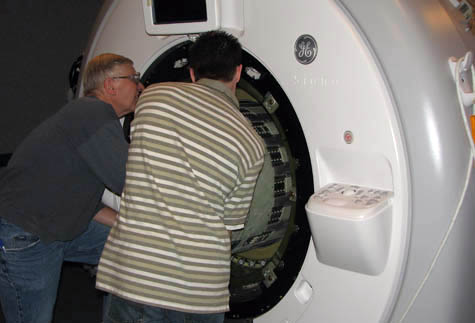
- notice: Do not use the air hose manifolds to remove the RF body coil.Fully remove the coil and set it aside on the patient end.
Figure 3. Removing RF body coil
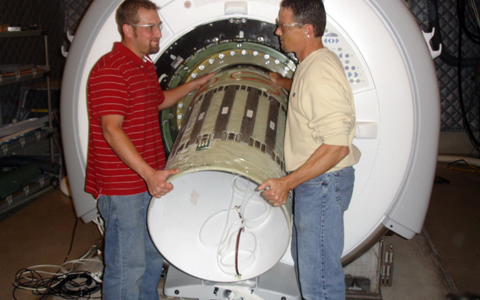
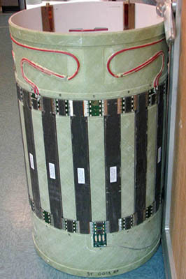
Figure 4. RF Body Coil on Patient End
Install new RF body coil
Procedure
- Slide the new body coil into the magnet bore. The DD bias lines are in the front and the I and Q connectors face the rear.
Figure 5. Sliding in RF body coil
- Align the I and Q connectors in the rear so they are as close to the 7 o'clock and 5 o'clock positions as visually possible.
Figure 6. Centering RF Body Coil
- If removed, re-install the four pop pins and install the bore lights to the body coil.
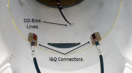
- Reconnect the DD bias lines and I and Q lines.
Figure 7. Reconnecting DD Bias Lines
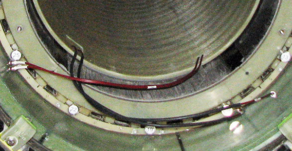
Figure 8. I and Q connectors
- Replace the front end bell. Refer to Front End Bell Removal and Installation. Confirm that the gap between the front end bell and the RF body coil is 2.5 +/- 0.5 mm with a target/desired gap of 2.0 mm.
- Replace the rear end bell. See Rear End Bell Removal and Installation.
- Press the RF body coil so the gap between the rear end bell and the RF body coil is 2.5 +/- 0.5 mm. The desired gap is 2.0 mm.
- Replace the split bridge. Refer to Bridge and Longitudinal Drive Belt Replacement.
- Remove LOTO. See the MR Service Safety Manual, PN 5452735.
Finalization
Procedure
- note: RF coil tuning can be done only by personnel who have successfully completed GE Healthcare’s training class for Body Coil Tuning and Stress Test, GEHC-TECH-AMSC-MR5037.Have the previously contacted, properly trained body coil tuning expert tune the RF body coil.
- Run TR Dynamic Disable Calibration.
- Run Troubleshooting the Daily Quality Assurance (DQA) II tool.
- Run LV Shim — Gradshim.
- Run System gain calibration.
- Run Echo Planar Test (EPT).
- Do SaveInfo.
- Do a quick head and body scan to ensure the system is functioning properly.