- id_12373888
- Version: 1.14
- Date: Jul 5, 2019 6:08:28 PM
PAC and SRI-4 Replacement
Prerequisites
| Required persons | Preliminary requirements | Procedure | Finalization |
|---|---|---|---|
| 1 | Not Applicable | 30 mins. for PAC; 45 mins. for SRI | 30 minutes |
| Item | Quantity | Effectivity | Part number | Manufacturer |
|---|---|---|---|---|
| Nonmagnetic service tool kit | 1 | - |
5112581 |
- |
| Item | Quantity | Effectivity | Part number | Manufacturer |
|---|---|---|---|---|
| PAC-2BV FRU | 1 | - | - | - |
| PAC-5 FRU | 1 | - | - | - |
|

Overview
Systems using DV26.0 software or later will use either the RRx receive chain or the DPP receive chain. To determine receive chain type, check the Receiver Type field in the Hardware Configure tab of Guided Install. RRx indicates the RRx receive chain, and DPP indicates the DPP receive chain.
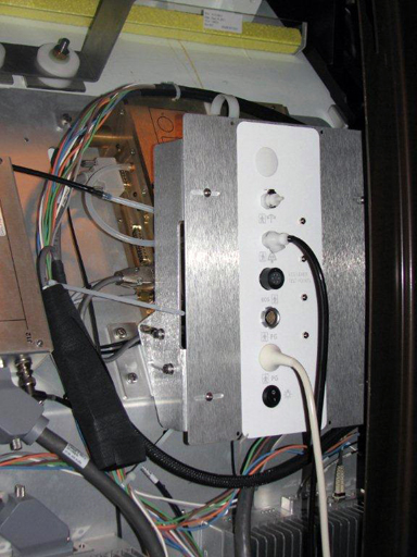
This procedure explains replacement of the physiological acquisition controller (PAC) assembly and the scan room interface (SRI-4) on a fixed site system.
Removal of the PAC
Procedure
- Perform LOTO on the RF amplifier and PEN cabinet. See the MR Service Safety Manual, PN 5452735.
- Disconnect all cables attached to the side of the PAC.
- Remove the screws securing the PAC and PAC interface to the electronic rack.
Installation of the New PAC
Procedure
- Place the PAC in the proper location and install it in reverse order from how it was removed.
- Attach all previously removed cables to the replacement PAC.
- Replace all previously removed covers and enclosure trim panels.
- Check the alignment of the PAC with the enclosure in all three
planes.
-
There are adjustment screws that allow for adjustment up/down, left/right, and in/out.
-
Adjust the PAC I/O panel so that it lines up with the slot in the enclosure in the left/right and up/down plane, and adjust it in/out so the gap between the I/O panel and the enclosure is less than 1 mm.
Figure 1. PAC Alignment (RRx Systems)
-
- Remove LOTO and restore power to the system. See the MR Service Safety Manual, PN 5452735.
Removal of the SRI
Procedure
- notice
- Perform LOTO on the PGR PDU/gradient subsystem. See the MR Service Safety Manual, PN 5452735.
- Disconnect the cables attached to the SRI.
Figure 2. SRI Cable Map
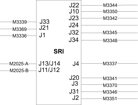
- Remove the four screws securing the SRI to the electronics rack. Unstrap and remove the SRI.
- Remove the straps from the SRI. They will be used when installing the new SRI.
 |
Installation of the New SRI
Procedure
- Place the new SRI in the proper location, and install in the reverse order of how it was removed.
- Mount the removed temperature sensor box on the replacement SRI.
- Reconnect the cables and replace the enclosure panels.
- Remove LOTO and restore power to the system. See the MR Service Safety Manual, PN 5452735.
Finalization
Procedure
- Perform a TPS Reset.
- Confirm that the reported problem has been resolved by running PAC or SRI diagnostics. In Service Methods, instructions for these diagnostics can be found in Troubleshooting > Diagnostics > Hardware Location > Magnet Room > PAC Diagnostic Tests and SRI Functional Diagnostics.
- Perform a Check Scan.