- id_12373883
- Version: 1.12
- Date: Jul 5, 2019 6:08:29 PM
LPCA Quick Disconnect Module Replacement
Prerequisites
| Required persons | Preliminary requirements | Procedure | Finalization |
|---|---|---|---|
| 1 | Not Applicable | 10 minutes | 30 minutes |
| Item | Quantity | Effectivity | Part number | Manufacturer |
|---|---|---|---|---|
| Non-magnetic service tool kit | 1 | - |
5112581 or 5113258 |
- |
| Item | Quantity | Effectivity | Part number | Manufacturer |
|---|---|---|---|---|
| Quick disconnect assembly | 1 | - |
See FRU manual |
- |
|

Overview
The LPCA quick release module is also referred to as the quick disconnect assembly, emergency release module, or quick disconnect connector. The LPCA quick disconnect modules allow for easy replacement of the coil connectors as they slide on and off their own track with minimal effort.
MR450, MR450w, MR750, and MR750w have both P1 and P2 coil connectors on the LPCA.
Procedure
- At the operator control panel (OCP), drive the LPCA and cradle
through the magnet bore to within 1 foot (30 cm) from the end of the
rear bridge.
-
This should provide enough room to work on the LPCA.
-
The LPCA will not move if the patient table is disconnected or not at the high limit prior to LPCA movement.
-
- At the foot of the table, twist or squeeze the cradle release handle to detach the cradle from the LPCA. Pull the cradle by hand to the home position so it is fully retracted onto the patient table.
- Undock the patient table and move it away from the magnet.
- Remove the four screws on the top of the LPCA cover.
Figure 1. LPCA Cover Screws
- Remove the cover.note:
To remove the cover, slide it slightly forward and lift the front of the LPCA to clear the hardware and then slide back and up.
- Grasp the quick disconnect module and pull and slide forward
as shown below to remove it from plastic guide track and fixed rear
connector assembly.
Figure 2. Quick Disconnect Module Removal Path

- Slide the new quick disconnect module onto the guide track, slide to the rear, and firmly seat into rear fixed connector.
- Place the new cover on the LPCA assembly starting at the rear and then the front. Take care to not pinch any of the wires in the rear of the LPCA. Attach the cover with the four screws.
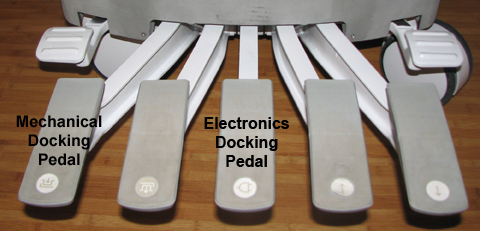
- Re-dock the patient table to drive the LPCA to the home position
and reattach to the cradle/patient table. Dock the table by pressing
the mechanical docking pedal. For tables equipped with P-connectors
or GEM coil, next engage the electrical dock connector by pressing
the middle foot pedal.
Figure 3. Electronic Docking Pedal
Finalization
-
Plug in all customer P-port connector coils into the new quick disconnect connectors. Lock the connectors to ensure the correct mating of the parts. Be aware that connector spindle receptacles require periodic lubrication as part of PM process. If the P-port does not lock, the spindle on the coil receptacle may need replacing. See ODU Connectors Cleaning and Replacement.
-
Perform a head or body scan. Scan faults can result from poorly seated quick disconnect modules.