- id_12374923
- Version: 1.3
- Date: Jul 5, 2019 6:08:29 PM
SRI-4 (Scan Room Interface) Replacement
Prerequisites
| Required persons | Preliminary requirements | Procedure | Finalization |
|---|---|---|---|
| 1 | Not Applicable | 30 minutes | 5 minutes |
| Item | Quantity | Effectivity | Part number | Manufacturer |
|---|---|---|---|---|
| Non-ferrous 19 mm Hex Head Wrench | 1 | - | - | - |
|

Overview
This procedure explains the replacement of the SRI (Scan Room Interface) assembly on a fixed site system.
Removal of SRI
Procedure
- Turn off power to the PDU. See the MR Service Safety Manual, PN 5452735, for information about LOTO on the PDU and gradient subsystem.
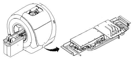
- note:The SRI is located under the left side of the magnet enclosure.
The PDU must be powered down completely to prevent damage to system electronics.
Figure 1. Location of SRI
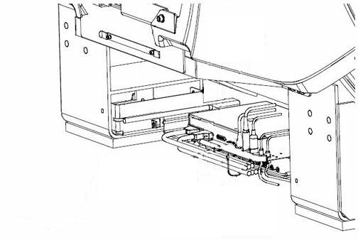
- Remove the left skirt covers Skirt Cover Removal and Install to expose the
tray that holds the PAC and SRI.
Figure 2. SRI Tray
- Disconnect the cables attached to the SRI.
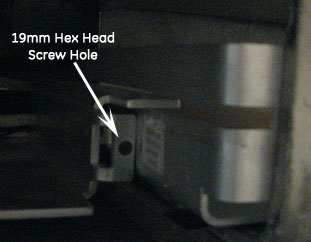
- The tray is held in place by one hex head screw on each slide.
Remove the two screws and slide the tray out for access to the SRI
board.
Figure 3. Screw Location
- Velcro holds the SRI to the tray. Lift the SRI off the tray and remove it.
Installation of New SRI
Procedure
- Place the new SRI in the proper location and install it by reversing the removal steps.
- Reconnect the cables.
- Slide the tray under the magnet and reinstall the two hex head screws.
- Replace the enclosure trim panels.
- Remove LOTO.
- Restore power.
Finalization
Procedure
- Perform a good bye scan. For Patient ID, use “test” to verify proper operation of coil ID.