- id_13105771
- Version: 3.0
- Date: Aug 29, 2019 1:34:37 AM
Front Cover Removal and Installation
Prerequisites
| Required persons | Preliminary requirements | Procedure | Finalization |
|---|---|---|---|
| 1 | Not Applicable | 15 (see Procedure Overview for details) minutes | 15 minutes |
| Item | Quantity | Effectivity | Part number | Manufacturer |
|---|---|---|---|---|
| Non-ferrous M5 Allen Wrench | 1 | - | - | - |
| Item | Quantity | Effectivity | Part number | Manufacturer |
|---|---|---|---|---|
| Front Cover | 1 | - | - | - |
|

Removal of the front cover typically takes less than 15 minutes if the front end of the split bridge has already been removed. If this step has not been performed, it takes at least 90 minutes to remove and replace the front cover.
The front cover and the front end bell can be removed independently of each other.
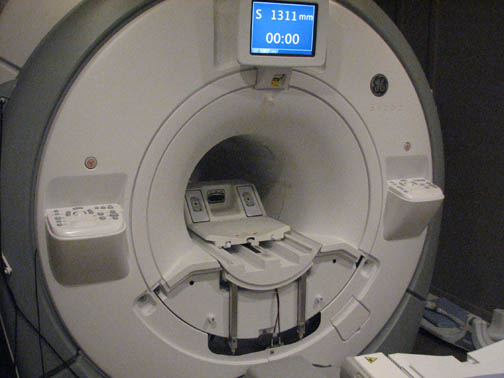
Front Cover without In-Room Display
Procedure
- Follow all LOTO procedures for the PDU. See the MR Service
Safety Manual, PN 5452735.
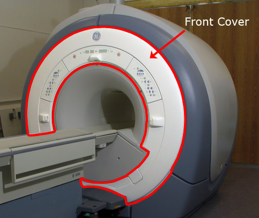
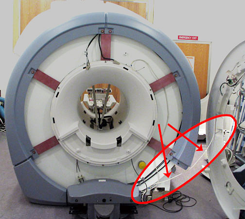
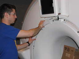
Figure 1. Front Cosmetic Cover
- Undock the patient table, and position it away from the magnet.
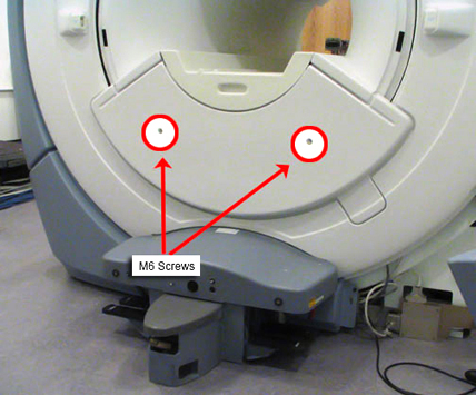
- Remove the two M6 screws that secure the front bridge cover.
Figure 2. Front Bridge Cover Screws
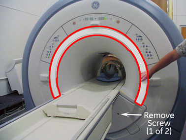
- Remove the front trim ring by pulling it away from the enclosure.
There are no bolts holding it in place.
Figure 3. Remove Trim Ring
- Remove the control panels.
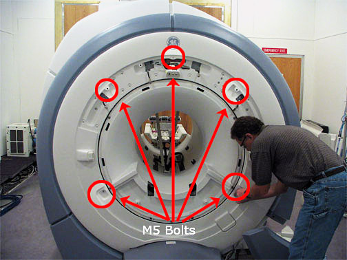
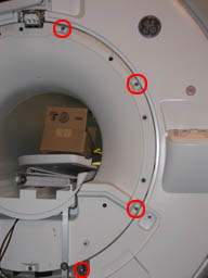
- Using an M5 Allen wrench, remove the 5 bolts that attach the
front cover to the turtle bracket.
Figure 4. Unbolting Front Cover
- After the 5 bolts have been removed, pull the front cover slightly
away from the magnet and locate the Conquest Voltage Regular Board
on the upper right side. Carefully remove JP1 from the board.
Figure 5. Voltage Conquest Board on Back of Front Cover
- Remove the front cover. Make sure the microphone cable connected
to the lower right side of the cover is not pulled.
Figure 6. Microphone Cord Attached to Cover
- To free the front cover from the microphone cord, you can either disconnect it from the rear pedestal (connector J9 on the remote intercom board), or detach it from the front cover.
- Reverse the above steps to install a replacement front cover.
Front Cover with In-Room Display
Procedure
- Follow all LOTO procedures for the PDU. See the MR Service
Safety Manual, PN 5452735.
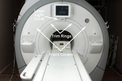
Figure 7. In-Room Display Front Covers
- Undock the patient table, and position it away from the magnet.
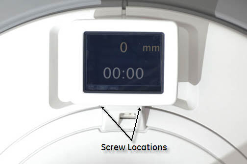
- Remove the alignment laser light cover by unscrewing two screws.
The cover is held in place by a popper on the lower left corner and
snaps off.
Figure 8. Remove Laser Light Cover
- Remove the two trim rings by pulling away from the enclosure.
They are held in place by poppers.
Figure 9. Remove Trim Ring
- Remove the two M6 screws that secure the front bridge cover.
See Figure 2.
Figure 10. Lower Cosmetic Cover Removed
- Remove the two control panel covers by unscrewing four screws
per panel. The covers are also held on by poppers and Velcro.note:
Be careful of the trackball control panel connection cables.
Figure 11. Unbolting Front Cover
- To free each front cover, disconnect the two cables that connect the control panel to the magnet.
- Reverse the above steps to install a replacement front cover.
Finalization
Procedure
- If the in-room display or trackball control panels are disconnected and then reconnected, reboot the host PC.
- After reboot, from the Common Service Desktop, select Diagnostics > Hardware > Magnet Room > In-Room Display.
The diagnostic displays the current status of the IRD and trackball connectivity. If the status is Not Installed, check the connections, reboot, and check the In-Room Display diagnostic again.