- id_13105835
- Version: 3.5
- Date: Feb 6, 2020 1:42:26 PM
Front end bell removal and installation
Prerequisites
| Required persons | Preliminary requirements | Procedure | Finalization |
|---|---|---|---|
| 2 | Not Applicable | 1.5 hours | Not Applicable |
| Item | Quantity | Effectivity | Part number | Manufacturer |
|---|---|---|---|---|
| Nonmagnetic Titanium Service Tool Kit, Large Set | - | - | 5112581 | - |
| Item | Quantity | Effectivity | Part number | Manufacturer |
|---|---|---|---|---|
| Front End Bell Assembly | 1 | - |
See FRU Manual |
- |
|

Procedure
- Perform LOTO on the PDU. See the MR Service Safety Manual, PN 5452735.
-
- Remove the bridge cover.
- Remove the bridge assembly. See Bridge and Longitudinal Drive Belt Replacement.
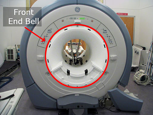
Figure 1. Front end bell
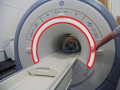
- For systems without an IRD, remove the front trim ring by pulling
it away from the enclosure. There are no bolts holding it in place.
Figure 2. Remove trim ring
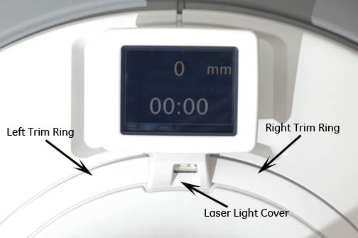
For systems with an IRD, remove the laser light cover, which is held on with 2 screws and a popper. The IRD has 2 front trim rings.
Figure 3. IRD laser light cover
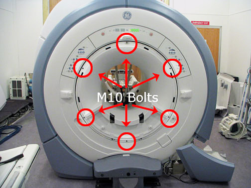
- Remove the six M10 bolts holding the front end bell to the turtle
bracket.
Figure 4. Front end bell bolt locations
- Remove the front body coil bias cable(s) and the body coil ID cable.
- notice: The front end bell is heavy. Avoid awkward body positioning. Use proper lifting techniques when moving the front end bell.Remove the end bell.note: Take care when removing or installing the end bell. Do NOT touch or move the body coil. Body coil tuning is dependent on body coil location.
- Reverse the steps to install the replacement front end bell. Confirm the gap between the front end bell and the RF body coil is 2.5 +/- 0.5 mm with a desired gap of 2.0 mm. Verify the proper fit of the covers.
If the gap measurement is outside the desired range, see RF Body Coil Replacement.
Finalization
- Remove LOTO from the PDU. See the MR Service Safety Manual, PN 5452735.
- Ensure the microphone and bore lights work.
- Complete a body scan (see Doing a check scan).