- id_12374919
- Version: 1.5
- Date: Jul 5, 2019 6:08:29 PM
PAC Replacement
Prerequisites
| Required persons | Preliminary requirements | Procedure | Finalization |
|---|---|---|---|
| 1 | Not Applicable | 30 minutes | 30 minutes |
| Item | Quantity | Effectivity | Part number | Manufacturer |
|---|---|---|---|---|
| Non-magnetic Service Tool Kit | 1 | - |
5112581 |
- |
| Item | Quantity | Effectivity | Part number | Manufacturer |
|---|---|---|---|---|
| PAC-2B or PAC-5 FRU | 1 | - |
See FRU manual |
- |
|

Overview
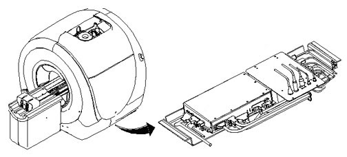
This procedure explains replacement of the Physiological Acquisition Controller (PAC) assembly. Discovery systems may have either a PAC-2B or a PAC-5. See the appropriate section of this procedure for replacement instructions.
PAC-5 units are backward compatible with PAC-2B. There is no impact with PAC hardware configuration in Guided Install.
Removal of PAC-2B or PAC-5
Procedure
- Perform LOTO on the RF amplifier and PEN cabinet. See the MR Service Safety Manual, PN 5452735.
- Locate the PAC under the left side of the magnet enclosure,
mounted to a movable sled with four pieces of Velcro.
Figure 1. Location of PAC
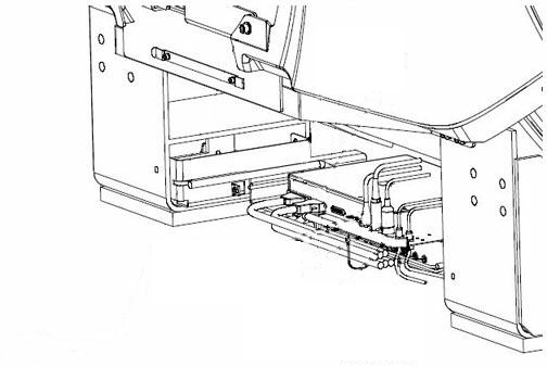
- Remove the left skirt covers and expose the tray that holds
the PAC and SRI. See Skirt Cover Removal and Installation.
Figure 2. PAC Tray
- Disconnect the cables attached to the PAC.
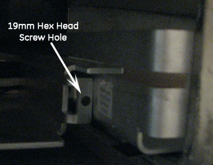
- Remove the two hex-head screws that hold the tray in place (one
on each slide), and slide the tray out for access to the PAC.
Figure 3. Screw Location
- Because the Velcro holds the PAC to the tray, lift the PAC off the tray and remove it.
Installation of New PAC-2B or PAC-5
Procedure
- notice
- Place the four pieces of Velcro from the FRU kit onto the SRI/PAC sled where the new PAC will be installed.
- Attach the remaining four Velcro pieces onto the PAC. Secure the PAC to the sled by mating all eight Velcro pieces.
- Attach all previously removed cables to the replacement PAC.
- Slide the tray with the PAC attached into its original position. Reinsert and tighten the hex-head screws.
- Replace all previously removed covers.
- Remove LOTO and restore power to the system. See the MR Service Safety Manual, PN 5452735.
 |
Finalization
Procedure
- Perform a TPS Reset.
- Confirm that the reported problem has been solved by running PAC diagnostics. In Service Methods, instructions for these diagnostics can be found in Troubleshooting > Diagnostics > Hardware Location > Magnet Room > PAC Diagnostic Tests.
- Perform a Check Scan.