- id_12374929
- Version: 1.6
- Date: Jul 5, 2019 10:24:08 PM
RF Hub Boards and Chassis Replacement
Prerequisites
| Required persons | Preliminary requirements | Procedure | Finalization |
|---|---|---|---|
| 1-2 | Not Applicable | 60-120 minutes | Not Applicable |
| Item | Quantity | Effectivity | Part number | Manufacturer |
|---|---|---|---|---|
| Non-Magnetic Service Tool Kit | 1 | - |
5112581 |
- |
| Item | Quantity | Effectivity | Part number | Manufacturer |
|---|---|---|---|---|
| RF Switch Board (RFSB, RFSB2, or RFSBv) | 1–2 | - |
See FRU Manual |
- |
| MC Driver Board (MCDB) | 1–2 | - |
See FRU Manual |
- |
| RF Control Board (RFCB) | 1 | - |
See FRU Manual |
- |
| Power Distribution Board (PDB or ePDB) | 1 | - |
See FRU Manual |
- |
| RF Hub Chassis | 1 | - |
See FRU Manual |
- |
|

| Condition | Reference | Effectivity |
|---|---|---|
|
Perform LOTO on the PDU. See the MR Service Safety Manual, PN 5452735. |
- | - |
Overview
When returning RF hub boards, use the original FRU packaging.
This document includes replacement procedures for:
-
RF switch board (RFSB) RF Switch Board
-
Multicoil driver board (MCDB) MC Driver Board
-
RF control board (RFCB) RF Control Board
-
Power distribution board (PDB) Power Distribution Board
-
RF hub chassis RF Hub Chassis
Figure 1. RF Hub Components
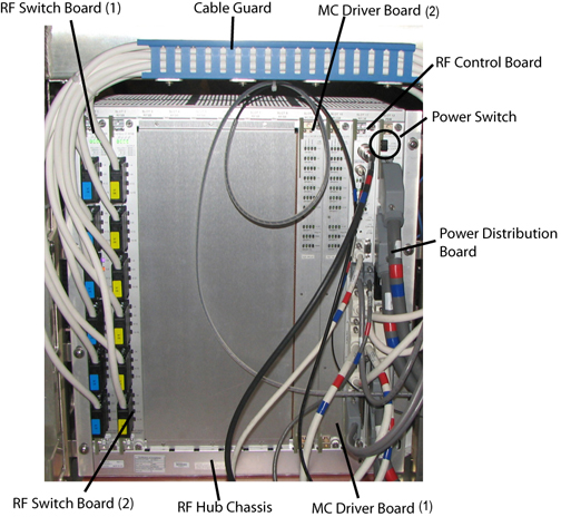
RF Switch Board
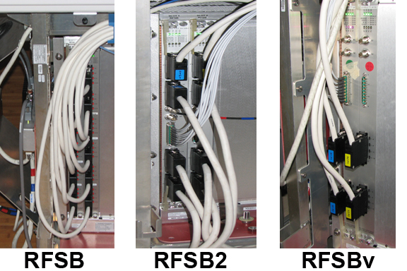
Multiple versions of the RF boards have been used, but the location in the RF hub chassis and the replacement procedures are the same.
Figure 2. RF Switch Board Versions
Removing RF Switch Board
Procedure
- notice
- Remove the side covers from the rear pedestal.
- Turn off the power switch on the power distribution board. See Figure 1.
- Remove the cables on the front of the RF switch board.
- Loosen the top and bottom screws on front of the RF switch board.
- Lift up on the top and bottom release levers to eject the RF
switch board.note:
The board will not eject unless both screws are thoroughly loosened.
- Slide out the RF switch board from the RF chassis.
- Place the board in an ESD bag and remove it from the magnet room.
 |
Installing RF Switch Board
Procedure
- Slide the new RF switch board into the RF chassis. Make sure the board is in the track.
- Line up the mechanical lever groove with the chassis edge, and
lower the levers to insert the board.
Figure 3. Groove on RF Board Lever
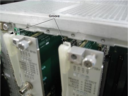 note:
note:Make sure the board is fully seated in the RF chassis.
- Tighten the top and bottom screws to secure the RF switch board to the RF chassis.
- Attach cables to the front of the RF switch board.
MC Driver Board
Removing MC Driver Board
Procedure
- Remove the side covers from the rear pedestal.
- Turn off the power switch on the power distribution board. See Figure 1.
- Loosen the top and bottom screws on the front of the MC driver board.
- Lift up on the top and bottom release levers to eject the MC
driver board.note:
The board will not eject unless both screws are thoroughly loosened.
- Slide out the MC driver board from the RF chassis.
- Place the board in an ESD bag and remove it from the magnet room.
Installing MC Driver Board
Procedure
- Slide the new MC driver board into the RF chassis.
- Line up the mechanical lever groove with the chassis edge, and
lower the levers to insert the board. See Figure 3.note:
Make sure the board is fully seated in the RF chassis.
- Tighten the top and bottom screws to secure the MC driver board to the RF chassis.
RF Control Board
Removing RF Control Board
Procedure
- Remove the side covers from the rear pedestal.
- Turn off the power switch on the power distribution board. See Figure 1.
- Remove the cables on the front of the RF control board.
- Loosen the top and bottom screws on the front of the RF control board.
- Lift up on the top and bottom release levers to eject the RF
control board.note:
The board will not eject unless both screws are thoroughly loosened.
- Slide out the RF control board from the RF chassis.
- Place the board in an ESD bag and remove it from the magnet room.
Installing RF Control Board
Procedure
- Slide the new RF control board into the RF chassis.
- Line up the mechanical lever groove with the chassis edge, and
lower the levers to insert the board. See Figure 3.note:
Make sure the board is fully seated in the RF chassis.
- Tighten the top and bottom screws to secure the RF control board.
- Attach the cables to the front of the RF control board.
Power Distribution Board
Removing Power Distribution Board (PDB or ePDB)
Procedure
- Remove the side covers from the rear pedestal.
- Turn off the power switch on the PDB. See Figure 1.
- Turn off the power switch on the scan room power supply (SRPS).
- Remove the cables on the front of the PDB.
- Loosen the top and bottom screws on the front of the PDB.
- Lift up on the top and bottom release levers to eject the PDB.
- Slide out the PDB from the RF chassis.note:
The board will not eject unless both screws are thoroughly loosened.
- For a PDB, remove the terminator (shunt connector) on slot J3.
The ePDB does not have a terminator.note:
Use this terminator (shunt connector) again when installing the new PDB.
- Place the board in an ESD bag and remove it from the magnet room.
Installing PDB
Procedure
- Slide the new PDB into the RF chassis.
- Line up the mechanical lever groove with the chassis edge, and
lower the levers to insert the board. See Figure 3.note:
Make sure the board is fully seated in the RF chassis.
- Tighten the top and bottom screws to secure the PDB to the RF chassis.
- Attach the cables to the front of the PDB.
- For a PDB, attach the previously used terminator on slot J3. The ePDB does not have a terminator.
- Turn on the SRPS.
RF Hub Chassis
Removing RF Hub Chassis
Procedure
- Remove the following RF hub boards:
-
RF switch board(s). See Removing RF Switch Board.
-
MC driver board(s). See Removing MC Driver Board.
-
RF control board. See Removing RF Control Board.
-
Power distribution board (PDB or ePDB). See Removing Power Distribution Board (PDB or ePDB).
-
- Remove any cables connected to the back of the RF chassis.
- On the other side of the rear pedestal, locate the vent intake connected to the RF chassis.
- Remove the three screws directly on top of the vent intake.
Figure 4. Vent Intake Screw Locations
- Pull the vent intake away from the RF chassis.
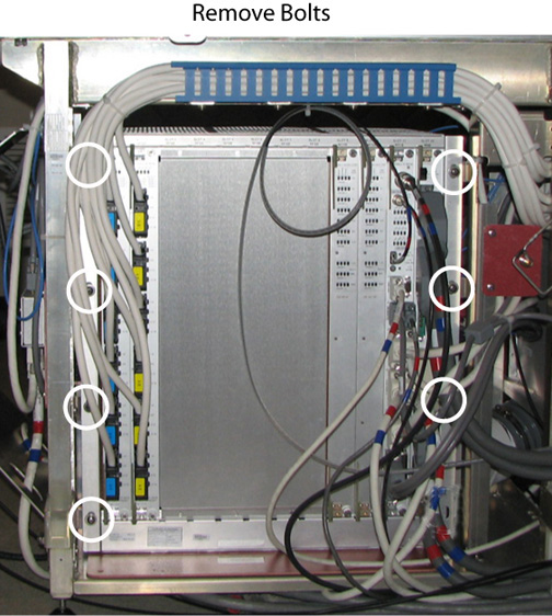
- Remove the seven bolts securing the RF chassis to the rear pedestal.
Figure 5. RF Chassis - Bolt Locations
- Remove the RF chassis from the rear pedestal.
Installing RF Hub Chassis
Procedure
- Position the new RF chassis in the rear pedestal.
- To connect the venting intake to the RF chassis, seat the vent in the RF chassis lip and secure the three screws directly on top of the vent intake. See Figure 4.
- Attach any previously installed cables to back of the RF chassis.
- Secure the seven bolts attaching the RF chassis to the rear pedestal. See Figure 5.
- Install the following RF hub boards:
-
RF switch board(s). See Installing RF Switch Board.
-
MC driver board(s). See Installing MC Driver Board.
-
RF control board. See Installing RF Control Board.
-
Power distribution board (PDB or ePDB). See Installing PDB.
-
Finalization
Procedure
- Turn on the power switch on the PDB.
- Replace the side covers on the rear pedestal.
- Remove LOTO. See the MR Service Safety Manual, PN 5452735.
- Perform a TPS reset.