- id_12374930
- Version: 1.1
- Date: Jul 5, 2019 10:03:32 PM
Table Interface Module Replacement
Prerequisites
| Required persons | Preliminary requirements | Procedure | Finalization |
|---|---|---|---|
| 1 | Not Applicable | 30 minutes | 10 minutes |
| Item | Quantity | Effectivity | Part number | Manufacturer |
|---|---|---|---|---|
| Non-Ferrous Tool Kit | 1 | - |
5112581 |
- |
| Item | Quantity | Effectivity | Part number | Manufacturer |
|---|---|---|---|---|
| Table Interface Module (TIM) | 1 | - |
5176474 |
- |
|


Overview
This procedure describes the replacement of the table interface module.
Procedure
- Perform LOTO on the RF amplifier and PEN cabinet. See the MR Service Safety Manual, PN 5452735.
- Remove two rear pedestal covers.
- Disconnect the cables attached to the TIM.
Figure 1. Location of TIM
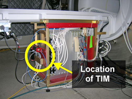
Figure 2. Close-Up of TIM
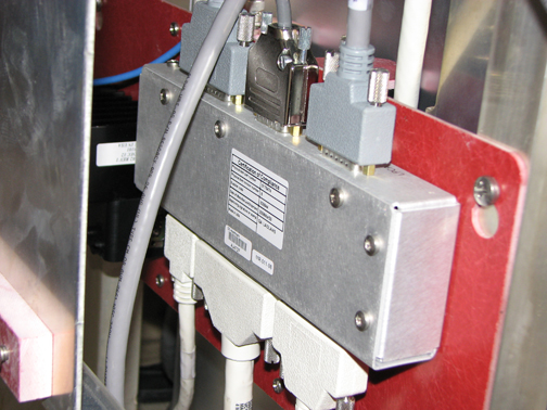
- Remove the five screws holding the TIM to the rear pedestal.
- Replace the TIM and follow steps Step 1 through Step 4 in reverse order.
Finalization
Remove LOTO. See the MR Service Safety Manual, PN 5452735.