- id_12373462
- Version: 1.3
- Date: Jul 5, 2019 6:08:29 PM
16- or 32-Channel Reroute Box (RRB) Replacement
Prerequisites
| Required persons | Preliminary requirements | Procedure | Finalization |
|---|---|---|---|
| 1 | Not Applicable | 30 minutes | 30 minutes |
| Item | Quantity | Effectivity | Part number | Manufacturer |
|---|---|---|---|---|
| Non-magnetic Service Tool Kit | 1 | - |
5112581 |
- |
| Item | Quantity | Effectivity | Part number | Manufacturer |
|---|---|---|---|---|
| 16-Channel Reroute Box | 1 | - |
See FRU Manual |
- |
| 32-Channel Reroute Box | 1 | - |
See FRU Manual |
- |
|
Removing RRB
Procedure
- Perform LOTO on the PGR cabinet. See the MR Service Safety Manual, PN 5452735.
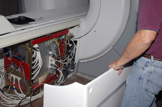
- Remove the side covers from the rear pedestal.
Figure 1. Removing Side Covers
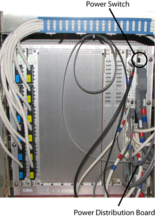
- Turn off the power switch on the power distribution board.
Figure 2. Power Switch on Power Distribution Board
- Remove all cables connected to the RRB (top, side 1, and side 2). Record the cable locations and run numbers for reinstallation.
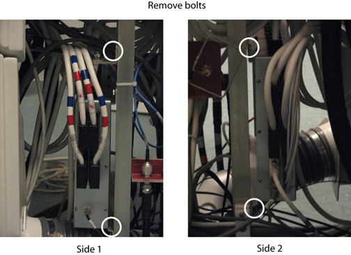
- Remove the four bolts holding the RRB to the rear pedestal.
Figure 3. Reroute Box (Side 1 and 2)
- While carrying the RRB out of the magnet room, stay as far away from the magnet as possible.
Installing RRB
Procedure
 caution
- While carrying the new box into the magnet room, stay as far away from the magnet as possible.
- Install the four bolts to secure the RRB to the rear pedestal. (See Figure 3.)
- Install all cables previously connected to the RRB (top, side 1, and side 2).
Finalization
Procedure
- Turn on the power switch on the power distribution board (see Figure 2).
- Replace the side covers on the rear pedestal.
- Remove LOTO from the PGR cabinet. See the MR Service Safety Manual, PN 5452735.
- Perform a head and body test scan.