- id_12373868
- Version: 1.16
- Date: Jul 5, 2019 10:03:32 PM
LPCA Cable Tracks Replacement
Prerequisites
| Required persons | Preliminary requirements | Procedure | Finalization |
|---|---|---|---|
| 1 | Not Applicable | 90 minutes | 30 minutes |
| Item | Quantity | Effectivity | Part number | Manufacturer |
|---|---|---|---|---|
| Assorted cable ties | Multiple | - | - | - |
| Non-magnetic service tool kit | 1 | - |
|
- |
| MCRv tool kit | 1 | - |
5182417 |
- |
| Item | Quantity | Effectivity | Part number | Manufacturer |
|---|---|---|---|---|
| Loctite 242 | 1 | - |
46-170686P1 |
- |
| Item | Quantity | Effectivity | Part number | Manufacturer |
|---|---|---|---|---|
| A-Port legacy cable track assembly | 1 | - |
See FRU manual |
- |
| Non-GEM P1 P2 cable track assembly | 1 | - |
See FRU manual |
- |
| 1.5T 32-channel cable track assembly | 1 | - |
See FRU manual |
- |
|


Overview
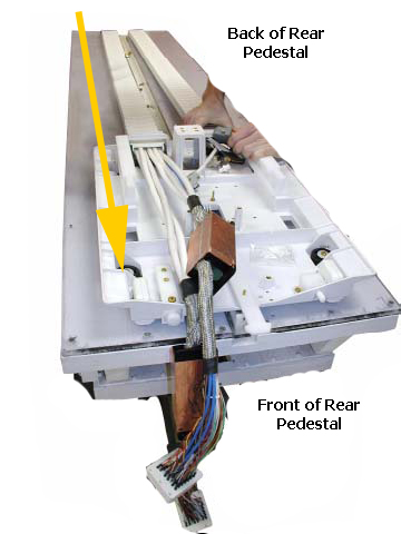
The LPCA of 32–channel systems contains two independent tracks. This procedure describes the replacement of either LPCA cable track. The tracks are FRU assemblies, meaning if one or more cables within a track fails, the entire track is replaced. Each track contains different cables, and each track has different connector types at both ends. Because of these differences, the procedure for replacing one cable track differs from the procedure for replacing the other cable track.
When looking at the LPCA from the front, the P1 and P2 coil connectors track is on the left side of the rear pedestal and is designated by two FRUs noted in Replacement Parts (see Table 6 for all cable types). The A-port and other associated cable tracks are located on the right side of the rear pedestal (see Table 7 for all cable types).
Remove Cable Track
Procedure
- At the operator control panel, drive the LPCA and cradle through
the magnet bore to within 1 foot (30 cm) of the end of the rear bridge.
This provides enough room to work on the LPCA.
The LPCA will not move if the patient table is disconnected or not at the high limit before LPCA movement.
- At the foot of the table, twist or squeeze the cradle release handle to detach the cradle from the LPCA. Pull the cradle by hand to the home position so it is fully retracted onto the patient table.
- Undock the patient table and move it away from the magnet.
- Perform LOTO on the rear pedestal. See the MR Service Safety Manual, PN 5452735.
- Perform system shutdown.
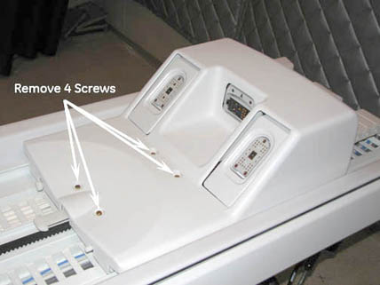
- Remove the LPCA cover.
Figure 1. LPCA Cover Screw Locations
- Remove both rear pedestal side covers.
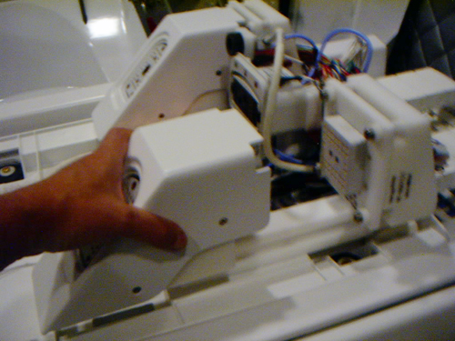
- Remove the P1 and/or P2 quick release modules. Use sufficient
force to pull the module forward to slide it off the track.
Figure 2. Remove the Quick Release Module
- To create enough space to remove and replace P1/P2 cable connectors,
do the following:
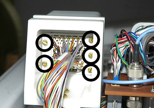
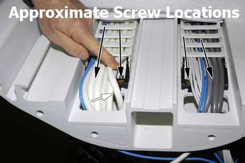
- At the rear of each cable mount bracket, remove two screws from
the left side and three screws from the right side, and then set the
cable connector aside.
Figure 3. Cable Connector Screws
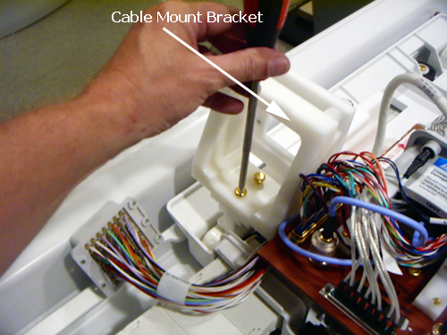
- Remove both bottom cable mount bracket screws, and then set the cable mount bracket aside.
Figure 4. Cable Mount Bracket Screws
- At the rear of each cable mount bracket, remove two screws from
the left side and three screws from the right side, and then set the
cable connector aside.
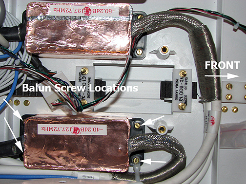
- Remove four slotted brass screws from the front and back of
the both baluns.
Figure 5. Balun Screw Locations
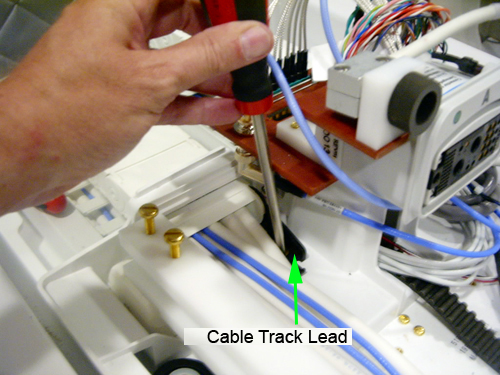
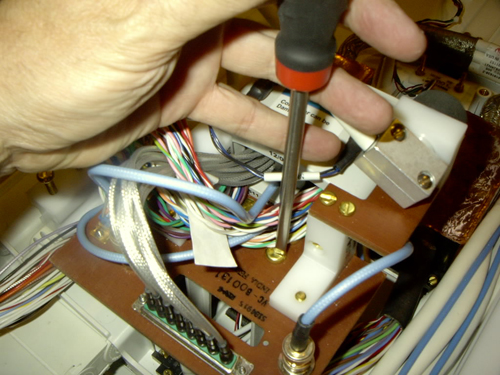
- Remove the two slotted head brass screws that secure the cable
track lead to the base of the LPCA.
Figure 6. Cable Track Lead Screw Locations
- Remove the two slotted head screws that secure the cable track
lead to the front of the rear pedestal bridge.
Figure 7. Bridge Cable Track Screw Locations
- Disconnect all cable connections that feed from the front end
of the cable track to points throughout the rear pedestal.note:
Take note of cable routing and tie wrap locations.
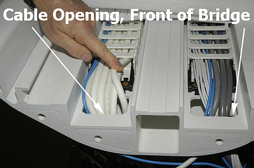
Table 6 16-Channel or 32-Channel LPCA Cable Track Connection Points 16-channel or 32-channel cable track assembly Other end positions PED-LPCA J5 PED J1 blue cable (on the right side as viewed from the patient table) PED load B blue cable (at the back of the rear pedestal) P1 A (reroute box), or PED-hub slot 1 P1 P1 B (reroute box) 32-channel only, or PED-hub-slot 2 P1 PED-hub-slot_11 J1, on RFCB slot 11 in RF hub PED-LPCA J4 P2 A (reroute box), or PED-hub-slot 1 P2 P2 B (reroute box) 32-channel only, or PED-hub-slot 2 P2 PED-hub-slot_11 J2, or RFCB slot 11 in RF hub - Feed loose end of cable connections up through the opening at
the front of the rear pedestal bridge and let them lay freely on the
bridge.
Figure 8. Cable Track Opening in Bridge
- Starting at the rear of the LPCA, pull cable connectors through the cable well of the bridge, under the LPCA, and out of the back of rear pedestal. Allow the cable track to hang freely.
- Starting from the front of the LPCA, pull the cable track (the
side that includes the baluns) through the opening on the LPCA in
a forward direction.
Figure 9. Removal Path of P1/P2 Cable Track
Removal of A-Port Connector Cable Track
Procedure
- note:Drive the LPCA and cradle into the bore to within 1 foot (30 cm) of the end of the bridge.
The A-port cable track is not used in systems with the DPP receive chain.
- At the foot of the table, twist or squeeze the cradle release handle to detach the cradle from the LPCA, and then pull the cradle by hand to the home position so that it is fully retracted back onto the table top.
- Undock the table and relocate it away from the magnet.
- Perform LOTO on the rear pedestal, and. See the MR Service Safety Manual, PN 5452735.
- Perform system shutdown.
- Remove the LPCA cover. See Figure 1.
- Remove both rear pedestal side covers.
- Remove the P1 and/or P2 quick release modules. Use sufficient force to pull the module forward so it slides off the track. See Figure 2.
- To create enough space to remove and replace the A-port connector
cable track, remove the two slotted brass screws from the bottom of
the P2 cable mount bracket as shown in Figure 4 and set it
aside.note:
Do not remove the connector from the cable mount bracket.
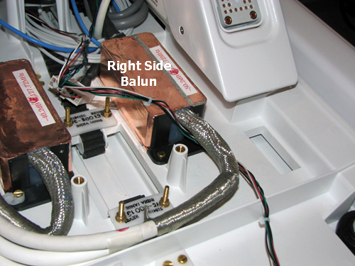
- Remove the four slotted brass screws from (right side) P2 balun
and then set it aside.
Figure 10. Right Side Balun
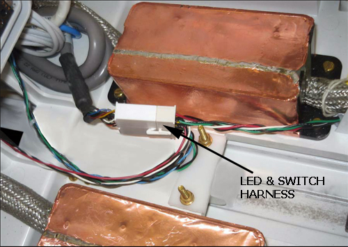
- Disconnect the LED and switch harness connector.
The LED and switch harness are part of the P1-only cable track of DPP receive chain systems.
Figure 11. LED and Switch Harness
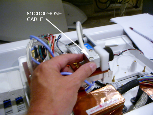
- Remove the microphone cable from the rear of the microphone.
The microphone cable is part of the P1-only cable track of DPP receive chain systems.
Figure 12. Microphone Cable
- Remove four slotted brass screws from top of LPCA bulkhead plate.
Carefully move wires out of the way when removing screws.
Figure 13. Top of Bulkhead Plate
- On the bottom of the bulkhead plate, remove the J1 connector first. Tilt the plate up to allow easier access to the retaining screws of J1.
- With the plate still tilted, remove the remaining connectors (J2, J4, and J5) from the bottom of the plate.
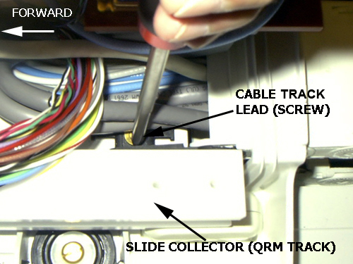
- Remove the two slotted head brass screws that secure the cable
track lead to the base of the LPCA.
Figure 14. Cable Track Lead Screws
- At the back of the LPCA, pull the cable track through the cable frame (opening) of the LPCA assembly and let it hang freely.
- Remove the two standard head screws that secure the cable track lead to the front of the rear pedestal bridge. See Figure 7.
- Disconnect all cable connections that feed from the front end
of the cable track to points throughout the rear pedestal.
Table 7 Cable Track Assembly Function and Other End Connection Points LPCA Connection Location Other End Position PED-LPCA J1 Reroute box J8, OR PED-hub slot 1-A PED-LPCA J5 PED J2 blue cable (on the right side as viewed from the patient table) PED-LPCA J3 PED J1 gray cable (J1 on the table interface box, LPCA interface) PED-LPCA J2 PED-hub slot 11 J6 (on RFCB in RF hub) Microphone J31 SRI (left side of magnet) PED-LPCA J4 Dummy load A (at back of rear pedestal, opposite side of table interface module) - Feed the loose end of cable connectors up through the opening
at the front of the rear pedestal bridge and let it lay freely on
bridge.note:
Maneuver the J6 connector so that it is level (straight) and angled in a diagonal to pass through the opening in the bridge.
- At the front of the rear pedestal bridge, pull the cable track through the cable well until the cable clears the underside of the LPCA.
Installation of New Cable Track
Procedure
- Move the replacement cable track into position.
- To ensure proper installation and reconnection of cables, reverse
the Removal procedures above (Step 19 or Remove Cable Track).note:
Wire tie the cables out of the way of the quick release module and slide mounting. The quick release module must slide freely without interference.
- Slide the quick release module to ensure it is fully inserted and there is no interference from the cable installation.
- Apply two drops of Loctite to each screw, then connect the four
screws that secure the track assembly to the bridge and LPCA.note:
Failure to apply Loctite to each cable chain screw before installation may result in screws working loose later and causing spike noise.
- Remove LOTO. See the MR Service Safety Manual, PN 5452735.
- Start up the software .
- Replace the LPCA cover.
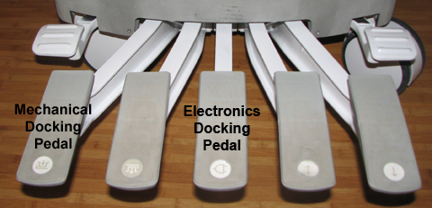
- Dock the patient table to drive the LPCA to the home position
and reattach it to the cradle/patient table. Be sure to dock the electronics
on 32-channel systems by pressing the foot pedal.
Figure 15. Electronics Docking Pedal
Finalization
Procedure
- Perform Check Scan.