- id_13105834
- Version: 3.4
- Date: Feb 6, 2020 1:49:29 PM
Rear end bell removal and installation
Prerequisites
| Required persons | Preliminary requirements | Procedure | Finalization |
|---|---|---|---|
| 2 | Not Applicable | 135 minutes | 15 minutes |
| Item | Quantity | Effectivity | Part number | Manufacturer |
|---|---|---|---|---|
| Nonmagnetic Titanium Service Tool Kit, Large Set | 1 | - | 5112581 | - |
| Item | Quantity | Effectivity | Part number | Manufacturer |
|---|---|---|---|---|
| Rear End Bell Assembly | 1 | - |
Refer to the FRU Manual |
- |
|
Procedure
- Perform LOTO on the PDU. See the MR Service Safety Manual, PN 5452735.
- Remove the front portion of the split bridge Bridge and Longitudinal Drive Belt Replacement.
- Remove the rear cosmetic covers Rear Cosmetic Cover Removal and Installation.
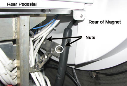
- Remove the nuts and washers holding the rear pedestal to the
magnet, and move the rear pedestal away from the magnet.
Figure 1. Remove nuts securing pedestal to magnet enclosure
 caution
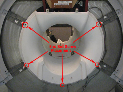
- Remove the five screws holding the rear end bell to the turtle
bracket.
Figure 2. Rear end bell screws
- notice
- Remove the two RF transmit cables from the RF body coil.
- Remove the patient air hose from the rear end bell.
- Remove the two RF coil cooling air hoses.
- Remove the rear end bell.
- Reverse the above steps to install the rear end bell. Confirm
the gap between the rear end bell and the RF body coil is 2.5 +/-
0.5 mm with a desired gap of 2.0 mm.
If the gap measurement is outside the desired range, see RF Body Coil Replacement.
- Verify proper fit of the covers.
 |
 |
Finalization
- Remove LOTO from the PDU. See the MR Service Safety Manual, PN 5452735.
- Verify that the speaker, patient air, and bore lights work.
- Do a body scan to ensure the system is working properly (see Doing a check scan).