- id_15271104
- Version: 2.7
- Date: Jan 17, 2020 10:41:14 AM
Dock Component Replacement
Prerequisites
| Required persons | Preliminary requirements | Procedure | Finalization |
|---|---|---|---|
| 2 | - | 60 minutes for 450/750/450w; 130 minutes for 450w GEM/750w GEM | - |
| Item | Quantity | Effectivity | Part number | Manufacturer |
|---|---|---|---|---|
| Non-Magnetic Tool Kit | 1 | - |
5112581 or 5113258 |
- |
| Item | Quantity | Effectivity | Part number | Manufacturer |
|---|---|---|---|---|
| Loctite 242 Threadlocker | (1) 0.5CC Tube | - | - | - |
| Fish Paper | As needed | - | - | - |
| Self-locking Cable Tie | As needed | - |
46-208758P5 |
- |
| Item | Quantity | Effectivity | Part number | Manufacturer |
|---|---|---|---|---|
| Dock Motor | 1 | - |
See FRU manual |
- |
| SPDT Snap Action Switch | 4 | - |
See FRU manual |
- |
| Dock Pedal Spring | 2 | - |
5448742 |
- |
|
| Condition | Reference | Effectivity |
|---|---|---|
|
All persons performing this procedure must complete GE-certified MR safety training. |
- | - |
Overview
This document describes how to perform the following procedures:
-
Dock Cover Removal: Dock Cover Removal
-
Dock Motor Replacement: Dock Motor Replacement
-
Dock Switch Removal and Installation: Dock Switch Removal and Installation
-
Dock Pedal Spring Replacement: Dock Pedal Spring Replacement
-
Dock Cover Reinstallation: Dock Cover Reinstallation
Dock Cover Removal
Procedure
 warning
- Remove the dock from the magnet room. See Dock Removal and Reinstallation.
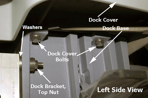
- Remove four bolts (two on each side) to unfasten the dock cover
from the dock base.
Figure 1. Dock Cover and Dock Base
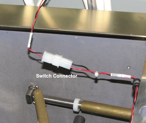
- While removing the dock cover, disconnect the switch connector.
Figure 2. Switch Connector
- Carefully remove the dock cover from the dock base and then
turn the dock cover upside down.note:
Be careful not to scratch the top of the cover. Lay down a cloth before putting the cover on the floor.
Dock Motor Replacement
Dock Motor Removal
Procedure
- warning
- Remove the dock from the magnet room. See Dock Removal and Reinstallation.
- Remove the dock cover. See Dock Cover Removal.
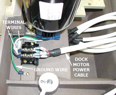
- Disconnect the dock motor power cable, terminal wires, and ground
wire.
Figure 3. Power Cable, Terminal, and Ground Wires
- Remove four screws (two on each side) from the dock motor mount
plate.
Figure 4. Dock Motor Mount Plate Screws
- Remove the dock motor.
- notice
- See Dock Motor Installation for instructions on how to reuse the coupling and install the new dock motor.
 |
Dock Motor Installation
Procedure
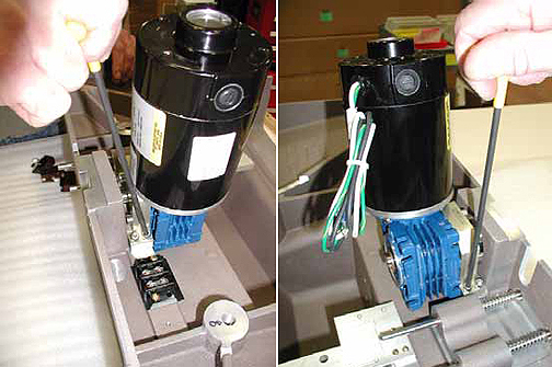
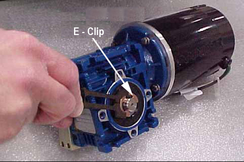
- Remove the e-clip from the end of the dock gearbox shaft on
the old dock motor using the blade of a slotted screwdriver. Secure
the e-clip during removal to prevent the clip from flying away when
pressured.
Figure 5. Old Dock Motor, Gearbox Shaft, and E-Clip
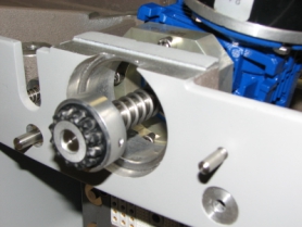
- Slide the dock gearbox shaft and key out of the dock motor and
set it aside. Remove four screws and mounting plate.
Figure 6. Dock Gearbox Shaft
- Apply Loctite 242 on the hex screws of the new motor.
Figure 7. Dock Motor, Mount Plate, and Screws
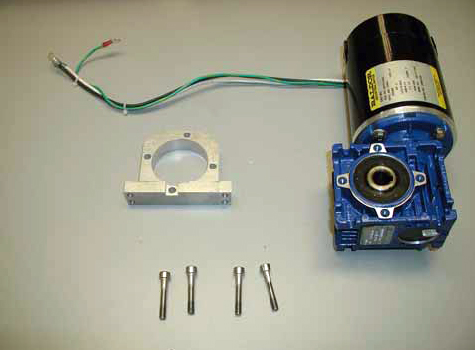
- Position the mount plate on the dock motor and fasten with the four screws.
- warning
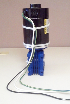
- Tie-wrap the cables as shown in Figure 8.
Figure 8. Dock Motor Cables Tie-Wrapped
- If replacing the shaft only, apply a small amount of anti-seize (from shaft assembly FRU kit) to the shaft key. If the complete dock motor assembly is being replaced, anti-seize is not required.
- Assemble the drive coupling on new shaft, then slide the new gearbox shaft, with spring and key, into the motor and replace the e-clip. See Figure 6.
- Apply Loctite 242 on the four mount plate screws, position the dock motor onto the dock cover, and then reattach the dock motor. See Figure 4.
- Reconnect the terminal wires, ground wire, and power cable to
original terminal strips. See Figure 3 and the following
illustration.
Figure 9. Wiring
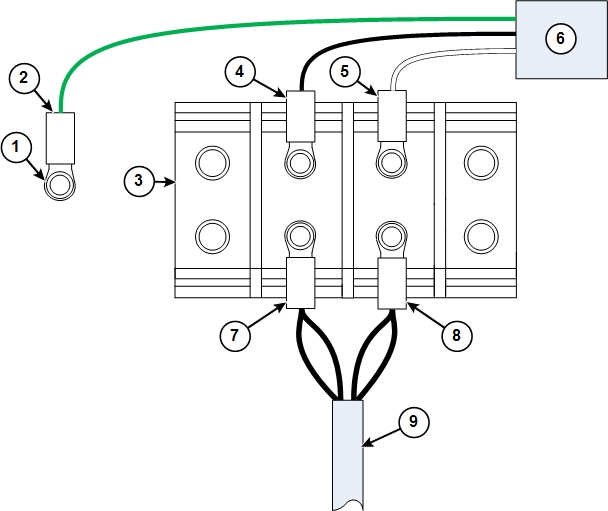
1 Ground stud 6 Dock motor 2 Ground wire from dock motor (green) 7 Dock motor cable connectors for position 1 3 Terminal block 8 Dock motor cable connectors for position 2 4 Black wire from dock motor (black) 9 Dock motor cable 5 White wire from dock motor (white) - Reconnect the switch connector.
- Reinstall the dock cover. See Dock Cover Reinstallation.
- Reinstall the dock. See Dock Removal and Reinstallation.
 |
Dock Switch Removal and Installation
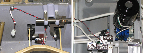
Switch 1 is located in the bottom casting. Switches 2, 3, and 4 are located in the dock cover.
Figure 10. Dock Switches
Procedure
- warning
- Remove the dock from the magnet room. See Dock Removal and Reinstallation.
- Remove the dock cover. See Dock Cover Removal.
- Remove the defective switch as required. Note the wire attachment locations on the switch terminals.
- When replacing switch 1 (inside the bottom casting):
- Place a square of fish paper between the switch and the mounting wall.
- Add Loctite 242 to each screw before replacing it.
- Tighten each screw until the screw stops without applying torque. Then turn the screw 30 degrees.
- When replacing switches 2, 3, or 4:
- Add Loctite 242 to each screw before replacing it.
- Push the switch toward the respective shaft while tightening
the screws.
Tighten each screw until the screw stops without applying torque. Then turn the screw 30 degrees.
- After installation, verify that all three switches activate and deactivate (an audible click should be heard) while cycling the shaft, in and out, at least three times (rotate the shaft approximately 120° for each cycle).
- Reconnect the wires to the switch terminals.
Table 7 Wire Chart for Switch Terminals One End Other End Pair No. Color Position Terminal Strip Range Term 511A590P Mark 1 BLU 1 AMP 66506–3 5.8 27 SW4 NO BLK 3 AMP 66506–3 5.8 27 SW4 COM 2 RED 4 AMP 66506–3 4.3 105 SW1 NO BLK 12 AMP 66506–3 4.3 105 SW1 COM 3 GRN 5 AMP 66506–3 5.8 27 SW3 NO BLK 13 AMP 66506–3 5.8 27 SW3 COM 4 WHT 6 AMP 66506–3 5.8 27 SW2 NO BLK 14 AMP 66506–3 5.8 27 SW2 COM 7 AMP 66506–3 Jump to Position 15 15 AMP 66506–3 Jump to Position 7 For more information, refer to the block diagrams for the site’s MR system.
- Reinstall the dock cover. See Dock Cover Reinstallation.
- Reinstall the dock. See Dock Removal and Reinstallation.
Dock Pedal Spring Replacement
Procedure
- warning
- Remove the dock from the magnet room. See Dock Removal and Reinstallation.
- Remove the dock cover. See Dock Cover Removal.
- Remove both of the old pedal springs from the dock pedals. The
springs are held in place only by spring tension. Pull up on one end
of each spring to remove them from the pedal assemblies.
Figure 11. Dock Pedal Spring Locations
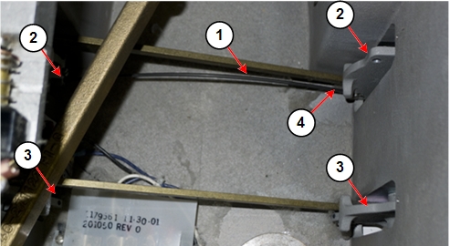
1 Dock pedal spring 3 Dock pedal assembly without spring 2 Dock pedal assembly with spring in place 4 Pull up on spring end to remove spring - notice
- Grasp one end of the dock pedal spring. Insert the end of the
spring into the hole at the end of one of the dock pedals.
Figure 12. Hole for Dock Pedal Spring
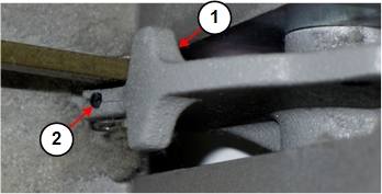
1 Dock pedal assembly 2 Hole for dock pedal spring Figure 13. Inserting Dock Pedal Spring
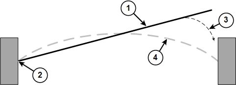
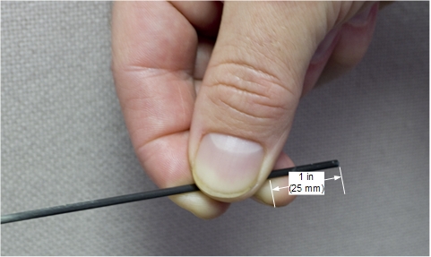
1 Dock pedal spring 2 Grasp one end of the spring and insert it into the hole at the end of one dock pedal. 3 Grasp the end of the spring approximately 1 inch (25 mm) from the end of the spring, and then gently insert the end into the hole in the other dock pedal. 4 Position of the dock pedal spring after installation - Grasp the other end of the dock pedal spring (at approximately
1 inch (25 mm) from the free end of the spring), and gently insert
it into the hole at the end of the other dock pedal. It is easier
to insert the spring into the pedal if you press down on the pedal.
Figure 14. Dock Pedal Spring Grasp Point
- Repeat Step 4 and Step 5 for the other pedal spring.
- Reinstall the dock cover. See Dock Cover Reinstallation.
- Reinstall the dock. See Dock Removal and Reinstallation.
|
Dock Cover Reinstallation
Procedure
- Reattach the switch connector. See Figure 2.
- Place the dock cover onto the dock base and reattach the dock cover bolts. See Figure 1.
- Reinstall the dock. See Dock Removal and Reinstallation.
Finalization
Finalization
-
Perform Dock Adjustments and Dock Hardware Adjustments as necessary.
-
Ensure the motor is functioning properly when docking the patient table and verify that lowering the table results in automatic retraction of the LPCA into the bridge.