- id_12374928
- Version: 1.17
- Date: Jan 17, 2020 10:20:24 AM
Magnet Microphone Replacement
Prerequisites
| Required persons | Preliminary requirements | Procedure | Finalization |
|---|---|---|---|
| 2 | Not Applicable | 60 to 120 minutes | Not Applicable |
| Item | Quantity | Effectivity | Part number | Manufacturer |
|---|---|---|---|---|
| Non-Ferrous Service Tool Kit | 1 | - |
5112581 |
- |
| Item | Quantity | Effectivity | Part number | Manufacturer |
|---|---|---|---|---|
| Epoxy | 1 | - |
46-282264P1 |
- |
| Nozzle | 1 | - |
46-320187P1 |
- |
| Item | Quantity | Effectivity | Part number | Manufacturer |
|---|---|---|---|---|
| A-Port Legacy Cable Track Assembly | 1 | - |
See FRU Manual |
- |
| Rear Microphone Assembly | 1 | - |
See FRU Manual |
- |
| Front Microphone Assembly | 1 | - |
See FRU Manual |
- |
Overview
This document describes the removal and installation of the rear and front microphones. The rear microphone is located inside the LPCA and the front microphone is attached to the front end bell. Both microphones connect to the SRI.
Replacing Rear Microphone
Before replacing a microphone, plug the replacement into the SRI (J31) to verify that the replacement microphone fixes the problem.
Procedure
- Drive the LPCA and cradle into the bore to within 12 in (30 cm) of the end of the bridge.
- At the foot of the table, twist or squeeze the cradle release handle to detach the cradle from the LPCA, and then pull the cradle by hand to the home position so that it is fully retracted onto the table top.
- Perform LOTO on the PDU. See the MR Service Safety Manual, PN 5452735.
- Remove the LPCA cover (four screws).
Figure 1. Removing LPCA Cover
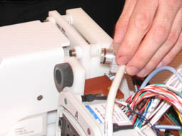
- Pull the microphone and housing out of the LPCA.
Figure 2. Removing Microphone and Housing from LPCA
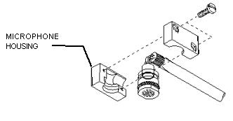
- Remove the microphone from its housing by gently pulling the
microphone to the rear.
Figure 3. Removing Microphone from Housing
- To remove and install the rear microphone, see LPCA Cable Tracks Replacement to replace the
cable track.note:
Individual cables cannot be ordered or replaced. Order the entire cable track.
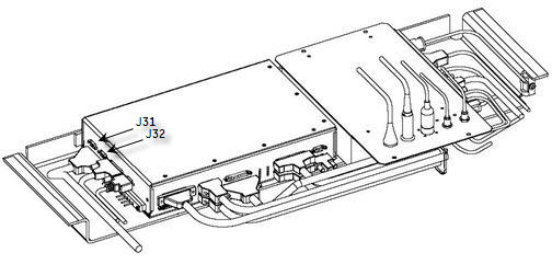
- The rear microphone attaches to the SRI (located under the magnet)
at J31.
Figure 4. SRI Cables
- Install the microphone into the housing.
- Install the microphone and housing into the LPCA.
- note:Install the LPCA cover and four screws.
Be sure to tuck in the receive cables fully, so as to not nick the exposed insulation on the cable track wires.
Removal and Installation of Front Microphone
Before replacing a microphone, plug the replacement into the SRI (J32) to verify that the replacement microphone fixes the problem.
Procedure
- Perform LOTO on the PDU. See the MR Service Safety Manual, PN 5452735.
- Remove the split bridge. See Bridge and Longitudinal Drive Belt Replacement.
- Disconnect the other end of the microphone cable at J32 located on the SRI. See Figure 4.
- Remove the front end bell, and handle the microphone cabling carefully while pulling it out. See Front End Bell Removal and Installation.
- Detach the microphone cable from the front cover.
- Carefully open the fasteners, and detach the microphone cable from the front cover.
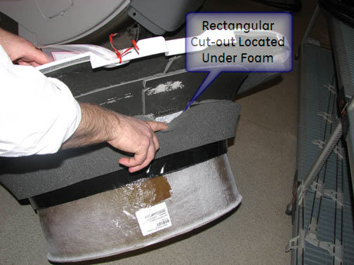
- Align the new microphone assembly in the rectangular cutout
located under the foam of the front end bell. See Figure 5.
- Place a 6 mm diameter pin through the end bell hole for the microphone to a 4 mm distance above nominal finished surface.
- Locate the microphone assembly over the pin, and glue in place with Plexus MA300 or MA310 adhesive.
Figure 5. Microphone Placement on Front End Bell
- Glue all around the microphone assembly bottom plate only. When the bonding agent has cured, remove the pin.
- Reverse Step 1 through Step 4 to complete the procedure.
Finalization
Finalization
-
Remove LOTO from the PDU. See the MR Service Safety Manual, PN 5452735.
-
Verify that the microphone is functioning properly.