- id_12374936
- Version: 1.5
- Date: Jul 5, 2019 6:08:29 PM
XRMB Manifold Replacement
Prerequisites
| Required persons | Preliminary requirements | Procedure | Finalization |
|---|---|---|---|
| 1 | - | 8 hours | - |
| Item | Quantity | Effectivity | Part number | Manufacturer |
|---|---|---|---|---|
| Floor Sign, Warning: Authorized Personnel Only | 1 | - |
Included in Safety Sign Kit (46-258770G4) or in 3.0T Warning Sign and Label Kit (2379494) |
- |
| XRMB Coolant Removal Kit (part of HEC) | 1 | - |
5269683 |
- |
| Non-Magnetic Tool Kit | 1 | - |
5112581 |
- |
| 5 Gallon Pail | 1 | - |
2239133 |
- |
| Item | Quantity | Effectivity | Part number | Manufacturer |
|---|---|---|---|---|
| XRMB Coolant Fluid (1 Gallon Container) (see Required Conditions) | 15 | - |
5174313 |
- |
| XRMB Coolant Fluid (5 Gallon Container) (see Required Conditions) | 3 | - |
5174313-2 |
- |
| XRMB Coolant Manifold Replacement Kit | 1 | - |
5316997 |
- |
| Item | Quantity | Effectivity | Part number | Manufacturer |
|---|---|---|---|---|
| XRMB Manifold | 1 | - | - | - |
|


| Condition | Reference | Effectivity |
|---|---|---|
|
Approximately 15 gallons of coolant fluid is needed for each XRMB installation. FEs must decide which type of container to order. |
- | - |
|
Power to the XGD cabinet is turned off and the LOTO procedures are implemented. See the MR Service Safety Manual, PN 5452735. |
- | - |
|
Coolant circulation pump is turned off and LOTO procedures are implemented. See the MR Service Safety Manual, PN 5452735. |
- | - |
Overview
This procedure describes the replacement/installation process of the XRMB manifold in the MR750 3.0T magnet.
XRMB Coil Water Removal
Procedure
- Remove magnet rear end bell. See Rear End Bell Removal and Install.
- Remove the bolts that secure the rear pedestal to the magnet
and position the rear pedestal away from the magnet.
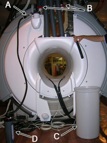
Figure 1. Bolts Securing Rear Pedestal to Magnet
A Rear pedestal B Bolts C Rear of magnet - Turn off the pumps at the Heat Exchange Cabinet (HEC) by pressing the appropriate key sequence
for the blowers, gradient coil, and power electronics drives:
Table 7 HEC Control Panel Key Sequence Part Key Sequence Blowers ▲ F1 Gradient Coil (GC) ▲ F2 Power Electronics (PE) ▲ F3 Press and hold ▲ while selecting the F-number key.
- Perform LOTO on the PGR cabinet. See the MR Service Safety Manual, PN 5452735.
- Turn off both PVC valves in the coolant supply and return lines
at the XRMB service end.
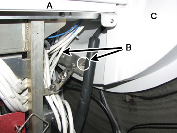
Figure 2. Disconnection Supply Manifold
A Pump-to-manifold adapter B Barbed fitting C Reservoir D Manual pump - Place an empty reservoir (about five gallon volume) close to the magnet service end to accept discharge coolant.
- Carefully disconnect the manifold supply and return lines (one at a time) from the barbed connections below the closed valves by loosening the hose clamps. Direct one line (either supply or return line) into the reservoir and empty as much coolant as possible into the reservoir.
- Obtain a one inch barbed fitting from the Coolant Removal Kit
and attach it to the other line. Connect the pump-to-manifold adapter
to the other line through the barbed fitting.
Figure 3. Manifold-to-Pump Connection
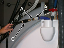
A Pump-to-manifold adapter B Barbed fitting C Manual pump connector - Attach the manual pump from the Coolant Removal Kit to the other end of the adapter (if not attached already).
- Start pumping air while observing coolant discharge.
- Continue pumping until no more coolant comes out, about 10 to 15 minutes.
- Disconnect the pump and the fitting. Place both into the Coolant Removal Kit bag.
- Measure the amount of removed coolant using a measuring flask (1000 ml). Record the measured volume in the service log.
Old Manifold Removal
Procedure
- With the magnet rear end bell and the rear pedestal removed, the XRMB manifolds are accessible.
- Ensure that the XGD heat exchanger pump is turned off and LOTO procedures are implemented for coolant line service. See the MR Service Safety Manual, PN 5452735.
- Ensure that both PVC valves in coolant supply and return lines at the XRMB service end are turned off and coolant has been purged from the XRMB coil.
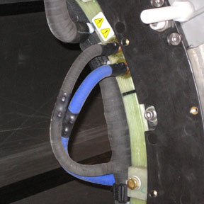
- Remove the black anchor straps that are securing the manifolds
to the XRMB coil.
Figure 4. XRMB Manifold
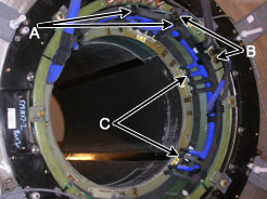
A Manifold anchor strap B Manifold-to-outer coil connection C Manifold-to-inner coil connection - notice
- Carefully cut open the heat shrinks at the manifold-to-inner
coil connections. A non-magnetic side cutter is required.
Figure 5. Removing Heat Shrink
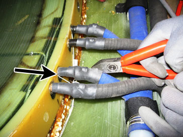
- The stainless steel hose clamp is exposed after the heat shrink
is removed. If this is a crimped clamp, it cannot be opened with a
screwdriver. Use a combination of non-magnetic screwdriver and needle
nose pliers to push the clamp away from the coil and slide it toward
the flexible hose.
Figure 6. Removing the Crimped Hose Clamp
- notice
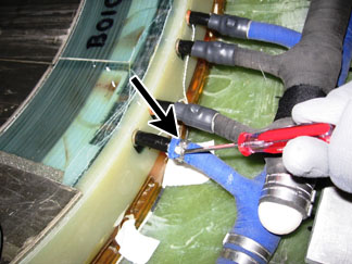
- After the hose clamp is open or pushed off the copper tube terminal,
disconnect the manifold hose from the tube terminal.
Figure 7. Disconnecting Manifold Hose
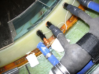
- For the remaining manifold hoses, remove the heat shrinks, push each clamp away from the coil and toward the flexible hose, and disconnect the manifold hose from XRMB inner coil.
- At the XRMB outer coil connection, remove the heat shrinks (if
there are any). Remove the black plastic rings at the water fittings.
Figure 8. XRMB Outer Coil Connection - Water Fittings
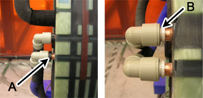
A Black plastic ring B Gap between inner and outer sleeve (black plastic ring removed) - Close the gap between the inner and outer sleeve of the fitting. Pull the plastic fitting off the copper tube terminal.
- The newer version of the manifold does not have the plastic
water fitting. Instead, the manifold is directly connected to the
tube terminal. In this case, remove the hose clamp and disconnect
the manifold hoses from the XRMB outer coil.
Figure 9. Manifold-to-Outer Coil Connection
 |
|
New Manifold Installation
Procedure
- Align the supply manifold (blue, PN 5268005) with the copper tube terminal at the XRMB inner coil. Push the manifold extension hoses onto the copper terminals.
- Apply the stainless steel clamps (provided with the Manifold Replacement Kit) to the manifold-to-inner coil connection and tighten the clamps with a non-magnetic screwdriver.
- Apply the rubber splicing tape (provided with the Manifold Replacement Kit) to the clamps and any exposed copper tube terminals.
- At the XRMB outer coil, connect the manifold to the copper tube as follows:
- For the newer version of the manifold (without the plastic water fitting), directly connect the manifold hoses to the outer coil tube terminals. Apply stainless steel clamps (provided with the Manifold Replacement Kit) to the manifold-to-outer coil connection and tighten the clamps with a non-magnetic screwdriver.
- Apply black anchor straps to secure the manifold to the XRMB inner coil.
- Repeat the above steps to install the return manifold (black, PN 5268152).
- Connect the supply and return manifold to the barbed fitting of the main coolant lines on top of the magnet. Secure the connection with stainless steel hose clamps. Open the main coolant line valves.
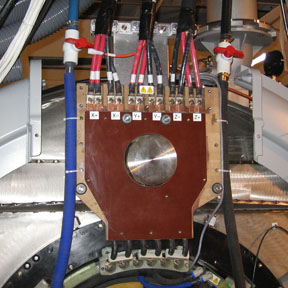
- Secure the extension hoses to the XRMB busbar board using a
tie wrap.
Figure 10. Main Coolant Line Connection
Finalization
Procedure
- Remove LOTO. See the MR Service Safety Manual, PN 5452735.
- Refer to HEC Coolant Fill and Coolant Leak Check to add coolant to the heat exchanger reservoir, turn on the heat exchanger pumps, and check the coolant system for leaks. The volume added should be close to that of the discharged coolant (refer to Step 13).
- Restore the magnet rear end bell. See Rear End Bell Removal and Install.
- Restore the rear pedestal by attaching the rear pedestal to the magnet with the two bolts Figure 1.
- Perform a check scan to ensure the system is functioning correctly.