- id_15271114
- Version: 3.0
- Date: Aug 29, 2019 1:34:23 AM
Dock Removal and Reinstallation
Prerequisites
| Required persons | Preliminary requirements | Procedure | Finalization |
|---|---|---|---|
| - | 30 minutes for 450, 750, 450w; 60 to 120 minutes for 450w GEM, 750w GEM | - |
| Item | Quantity | Effectivity | Part number | Manufacturer |
|---|---|---|---|---|
| PPE – safety glasses and gloves | 2 | - | - | - |
| Non-magnetic Service Tool Kit | 1 | - |
5112581 |
- |
| IF NEEDED: Magnet Dock Bolt Cutting Kit (contains hacksaw, extra blade, tack cloth, assorted nuts, washers) | 1 | - |
5435943 |
- |
| MCRv Tool Kit | 1 | (For 1.5T) |
5182417 |
- |
| MCRv Tool Kit | 1 | (For 3.0T) |
5182417-2 |
- |
| Item | Quantity | Effectivity | Part number | Manufacturer |
|---|---|---|---|---|
| Masking tape | 1 | - | - | - |
|
Overview
This document contains procedures to remove and reinstall the patient table dock, which is necessary for replacement of hardware internal to the dock such as switches, motor, and springs.
During this procedures, the following tasks are performed:
-
Prepare the dock assembly for removal.
-
Cut the anchor stud, if necessary.
-
Remove the patient table dock assembly from the magnet room.
-
Reinstall the patient table dock assembly.
-
Confirm that the patient table dock assembly is installed correctly and the system is working properly and ready to be turned over to the customer.
The dock assembly is the most ferrous object in the magnet room. Utmost care must be taken when following these procedures. Never allow the end of the dock assembly (closest to the magnet) to come off the floor while in the magnet room. During the procedure, you will be asked to lift the front end of the dock assembly; the front end of the dock should never be lifted more than 3 inches (7.6 cm) while in the magnet room.
Preparing Dock for Removal
Procedure
- Perform LOTO on the RF amplifier and PEN cabinet. See the MR Service Safety Manual, PN 5452735.
- Undock the patient table, and move it away from the magnet and out of the path between the dock and the magnet room exit door.
- On the magnet, remove the right and left side skirt covers. See Skirt Cover Removal and Installation.
- Disconnect all cable connections from the magnet and the rear
pedestal to the rear of the dock.
Depending on the site’s system, there are different configurations possible:
-
Systems that have the cable interface for receive cables on magnet front right foot
-
Systems that have the dock receive cables going all the way to the RF hub
-
Systems that have SRI cables going to magnet left front foot
Remove the associated cables that pertain to the site’s system configuration.
-
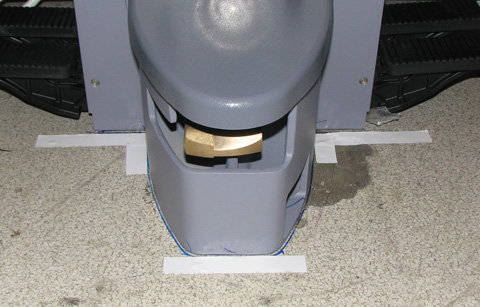
- To assist in repositioning the dock during reinstallation, mark
the placement of the dock on the floor. Depending on the site’s
need, place tape on floor at the leading edge of the dock, and on
the right and left sides. Both are shown in the illustration.
Figure 1. Tape to Mark Original Position of Dock
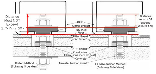
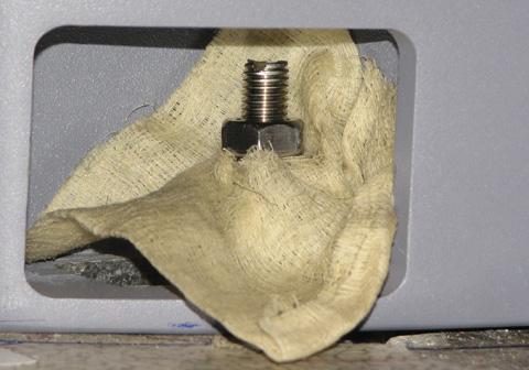
- Visually check the height of the anchor stud that bolts the
dock assembly to the floor. The height of the stud should not exceed
2.75 in (7 cm) as measured from the floor or 2 in (5 cm) as measured
from the top of the clamp bracket.
Figure 2. Measure Height of Anchor Stud
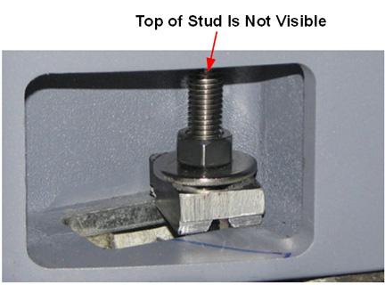
If you do not have something with which to measure the anchor stud, look straight into the opening on the right side of the dock assembly. If you cannot see the top of the stud, the stud is too tall and might need to be cut.
Figure 3. Example of Stud That Must Be Cut
- If the height of the stud does NOT exceed 2.75 in (7 cm) (as
measured from the floor), proceed to Removing Dock from Magnet Room.
If the height exceeds 2.75 in (7 cm) (as measured from the floor):
-
Loosen the stud anchor nut with a non-ferrous wrench and unscrew it a few turns. If the nut and washers are in the way, remove them.
-
Try to remove the anchor stud with your fingers. Do not use any tools, because this could damage the anchoring system.
-
If you cannot remove the anchor stud, try to lower the anchor stud by turning the stud to make it shorter. Use only your fingers to turn the screw, because a tool might damage the anchoring system.
-
If you are able to remove or lower the stud, proceed to Removing Dock from Magnet Room.
-
If you cannot remove the stud or lower the stud, order the Magnet Dock Bolt Cutting Kit (PN 5435943) and proceed to Cutting Anchor Stud.
-
Cutting Anchor Stud
Procedure
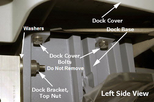
- notice
- At the rear of the dock, use a ¾ inch non-ferrous wrench
to LOOSEN (not remove) 4 nuts (2 on each side) from the dock bracket
bolts.
Figure 4. Dock Brackets
- Loosen the nut on the stud anchor, if not already loosened.
- Push the dock assembly as far to the left as possible, positioning the stud anchor close to the opening. The stud needs to be as accessible as possible to ease the cutting procedure.
- Retighten the four (4) nuts on the bolts attaching the dock assembly to the magnet and, also, retighten the nut on the stud anchor. This prevents any movement of the dock assembly during the cutting procedure.
- The stud removal kit has a selection of different nuts. Select
a spare nut of the same dimension and threading as the anchor stud.
Attach it to the stud on top of the original nut. The top of the second
nut is used as the cutting mark.
If you do not have a spare nut that fits, remove the anchor stud nut, remove the washers, and thread the nut completely to the base of the stud. Then cut a small hole in the tack cloth and fit it over the stud. Place all the washers from the kit on the stud, over the tack cloth, as shown in Figure 5, to achieve the height of the additional nut.
- Cut a small hole in the center of a tack cloth square and fit
it over the top of the stud. The tack cloth will catch and retain
the metal filings as the stud is cut.
Figure 5. Second Nut on Anchor Stud
- Insert a second tack cloth square into the entrance, covering as much of the area as you can. These pieces of tack cloth will help trap any metal filings.
 warning
- caution
- caution
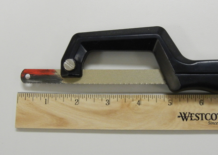
- note:Confirm that the end of the blade extends about 1.5 inches (3.8 cm) beyond the top edge of the hacksaw. This is the portion of the blade that you will use to cut the anchor stud.
If the blade on the hacksaw becomes dull during the cutting process, leave the magnet room, disassemble the hacksaw, and flip the blade so a new set of teeth are now cutting the stud.
Figure 6. Extended Blade on Hacksaw
- Cut the stud just above the top nut.
- Carefully remove the pieces of tack cloth. Roll them up to contain any loose metal filings.
- Use a clean piece of tack cloth to wipe the area, removing any metal filings that might be present.
- Remove the cut end of the stud and the soiled tack cloth from the magnet room.
- Remove the second nut.
If you used the washers from the kit, remove the washers and discard them. Place the original washer on the anchor stud and reattach the nut.
 |
Removing Dock from Magnet Room
Procedure
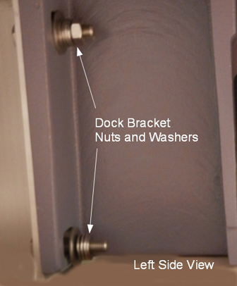
- note:At the rear of the dock, use a ¾ inch non-ferrous wrench to remove 4 nuts (2 on each side) from the dock bracket bolts. Make note of the number of washers between the dock mounting bracket and the dock at each stud location.
Remove only the nuts from the rear of the dock that connect it to the dock brackets. You do not have to remove the dock brackets from the magnet.
Figure 7. Dock Bracket Nuts and Washers
Figure 8. Dock Brackets at Rear of Dock
- Remove the nut, washers, and clamp bracket from the anchor stud.
If the site has followed the Pre-Installation Manual and the anchor is a two-part assembly, remove the anchor stud (bolt) from the female sleeve anchor, using hand-force to turn the stud. This allows the dock to remain flush with the floor during removal. This is the preferred method. If you can remove the anchor stud, proceed to Step 8.
Otherwise, the dock must be lifted slightly to clear the anchor stud, as described below.
- warning
- warning
- Applying pressure to the top of the dock, completely remove
all dock attachment bolts, then remove washers.
Make a note of the number of washers that are placed between the dock and the bracket, because they will need to be reinstalled in the same quantities and locations.
See Figure 4 for location of washers and Figure 9 for position of field service personnel when removing hardware.
note:Remove only the nuts from the rear of the dock that connect it to the dock brackets. Do NOT remove the dock brackets from the magnet.
Figure 9. Apply Pressure to Top of Dock and Remove Bolts
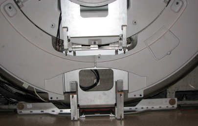
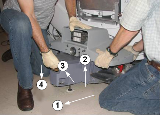
- Use two people to pull the dock away from the magnet and hold down the dock assembly. Move the dock until the stud in the front is hitting the inner frame (labeled as 1 in Figure 10).
- warning
- warning
- Use two people to lift the front of the dock JUST ENOUGH to
clear the top of the stud in the floor (labeled as 2 in Figure 10). Avoid scraping the dock assembly or the base of the magnet.
Do not lift the front of the dock more than 3 inches (7.6 cm) from the floor. The rear of the dock must remain in contact with the floor.
- Use two people to move the dock to the left, just beyond the anchor stud (label as 3 in Figure 10).
- Use two people to lower the dock back on the floor immediately
to the side of the anchor stud (labeled as 4 in Figure 10).
Figure 10. Pull Dock Away from Magnet, Lift to Clear Stud, Place on Floor to Side of Stud
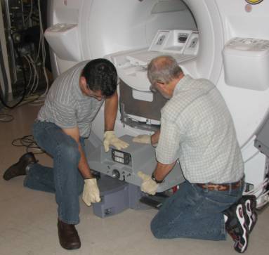
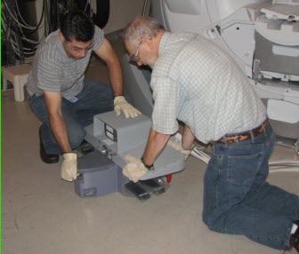
- With two field engineers, one holding each side of the dock,
slowly and deliberately slide the dock away from the magnet, keeping
downward pressure on the top of the dock assembly. Use care as the
loose cables will be trailing behind the dock. Move the dock to a
distance equivalent to where the foot of the patient table would normally
be located.
Figure 11. Apply Pressure to Top of Dock
- When the distance between the dock and the magnet is at least equivalent to the distance between the magnet and where the foot of the patient table would normally be located, both field engineers may slowly lift the dock from the floor and exit the room.
- caution
- Make sure to wear gloves during this cleaning procedure.
If the anchor stud was cut, return to the magnet room with a piece of tack cloth and clean the floor area where the dock was to remove any metal filings that may be present.
Also, clean the bottom of the dock assembly and the area of the anchor stud to remove any remaining metal filings before returning it to the magnet room.
 |
|
Reinstalling Dock
Procedure
- warning
- note:With two field engineers, one holding each side of the dock, enter the magnet room and place the dock on the floor where the foot of the patient table would normally be located.
Any time you remove the dock from the magnet, you must check levelness and alignment of the dock and patient table when you reattach the dock to the magnet.
- With two field engineers, one applying vertical downward pressure to each side of the dock, slide the dock toward the magnet front.
- Position the dock to clear the floor stud. There are two ways
to do this:
- If the site has followed the Pre-Installation Manual (PIM), then when reinstalling the dock it should be possible to remove the top portion of the stud. If this is the case, then continue to maintain pressure on the top of the dock and carefully slide the dock against the base of the magnet. Reinstall top portion of anchor stud.
- If the site has an anchor stud that protrudes vertically from
the floor and cannot be removed, a non-conformance MUST be raised
with the customer and the anchor must be fixed to comply with the
Pre-Installation Manual before any future servicing of the dock. To
complete the task this time, follow these instructions per the reverse
directions shown in Figure 12.
Figure 12. Positioning Dock When Anchor Stud Cannot Be Removed
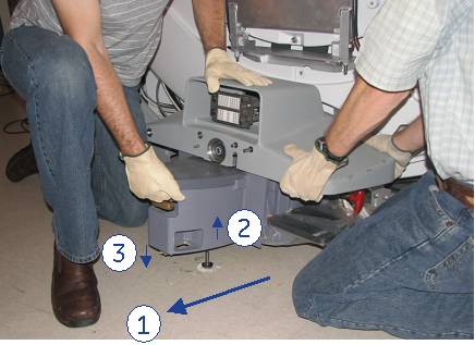
-
While maintaining pressure on the top of the dock, position the dock against the base of the magnet to the side of the floor stud at the front of the dock (number 3).
-
Lift the dock just enough to clear the top of the stud in the floor (number 2).
-
While rotating the dock, align the hole at the base of the dock with the stud and place the dock down into position and re-anchor the dock (number 1).
-
- Reattach the nuts and washers to the dock bracket.note:
Take care with the washers that are placed between the dock and the bracket. Ensure that the same number of washers is installed behind the dock on each bolt.
Figure 13. Dock Brackets
- While placing continuous downward force on the top of the dock assembly, reconnect all cables from rear of dock to magnet I/O panels and rear pedestal.
- Replace magnet right and left side skirt covers.
- Dock the patient table.
- Remove LOTO from the RF amplifier and PEN cabinet (magnet room). See the MR Service Safety Manual, PN 5452735.
Finalization
Procedure
- Perform all finalization steps required in other referenced procedures.
- Ensure that dock motor on switch operates properly when table up pedal is pressed.
- Perform dock adjustments. See Dock Centering and Dock Hook Tension Adjustment. Confirm proper alignment and centering for the dock and table.
- Verify that cradle travel into the bore is smooth.
- Perform Laser Light Alignment.
- Perform DQA II Tool and Troubleshooting.
- Perform Check Scan.