- id_12373862
- Version: 1.13
- Date: Jul 5, 2019 10:03:32 PM
LPCA Components Replacement
Prerequisites
| Required persons | Preliminary requirements | Procedure | Finalization |
|---|---|---|---|
| 1 | Not Applicable | See Procedure Overview | 20 minutes |
| Item | Quantity | Effectivity | Part number | Manufacturer |
|---|---|---|---|---|
| Non-magnetic service tool kit | 1 | - |
5112581 |
- |
| Item | Quantity | Effectivity | Part number | Manufacturer |
|---|---|---|---|---|
| DVMR LPCA (multiple) | 1 each | - |
See FRU manual |
- |
| LPCA cover (RRx systems) | 1 each | - |
See FRU manual |
- |
| LPCA cover (DPP systems) | 1 each | - |
See FRU manual |
- |
| A-port bezel (RRx systems) | 1 each | - |
See FRU manual |
- |
| LED and switch harness (RRx systems) | 1 each | - |
See FRU manual |
- |
| Switch harness (DPP systems) | 1 each | - |
See FRU manual |
- |
| Sub-D plate | 1 each | - |
See FRU manual |
- |
| Plunger assembly | 1 each | - |
See FRU manual |
- |
| Cradle latch | 1 each | - |
See FRU manual |
- |
|
Overview
LPCA FRU procedures and timings for DPP receive chain systems:
-
LPCA cover: procedure timing - 10 minutes
-
Switch harness: procedure timing - 20 minutes
-
Cradle latch: procedure timing - 15 minutes
-
Sub-D plate: procedure timing - 20 minutes
-
Plunger: procedure timing - 15 minutes
LPCA FRU procedures and timings for RRx receive chain systems:
-
LPCA cover: procedure timing - 10 minutes
-
A-port bezel: procedure timing - 30 minutes
-
LED and switch harness: procedure timing - 20 minutes
-
Cradle latch: procedure timing - 15 minutes
-
Sub-D plate: procedure timing - 45 minutes
-
Plunger: procedure timing - 15 minutes
Removing and Replacing the LPCA Cover
Procedure
- At the operator control panel, drive the LPCA and cradle through
the magnet bore to within 1 foot (30 cm) from the end of the rear
bridge. This should provide enough room to work on the LPCA.
The LPCA will not move if the patient table is disconnected or not at the high limit before LPCA movement.
- At the foot of the table, twist or squeeze the cradle release handle to detach the cradle from the LPCA. Pull the cradle by hand to the home position so it is fully retracted onto the patient table.
- Undock the patient table and move it away from the magnet.
- Remove the four screws on the top of the LPCA cover.note:
The LPCA cover for DPP systems does not include the A-port.
Figure 1. LPCA Cover Screws
- Remove the cover.note:
To remove the cover, slide it slightly forward and lift the front of the LPCA to clear the hardware, and then slide back and up.
- Place the new cover on the LPCA assembly starting at the rear and then the front. Take care to not pinch any of the wires in the rear of the LPCA.
- Attach the cover with the four screws.
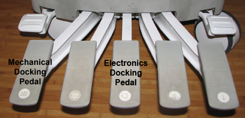
- Re-dock the patient table to drive the LPCA to the home position
and reattach to the cradle/patient table. Dock the table by pressing
the mechanical docking pedal. If the table is equipped with P-connectors
or the GEM coil, engage the electrical dock connector by pressing
the middle foot pedal.
Figure 2. Electronic Docking Pedal
A-Port Bezel
Removing A-Port Bezel
Procedure
- note:Remove the LPCA cover (see Removing and Replacing the LPCA Cover).
The A-port bezel is not found on systems that use the DPP receive chain. If you are working on a DPP system, skip this step and go directly to Removing and Replacing LED and Switch Harness, Step 1.
- notice
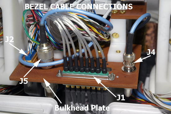
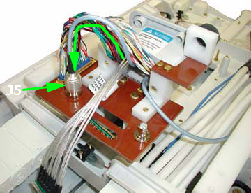
- Behind the A-port bezel, disconnect all cable connections (J1,
J2, J4, and J5) from the sub-D (or bulkhead) plate. A 3/16 nut driver
is required to remove J1 and J2.
Figure 3. A-Port Bezel Cables
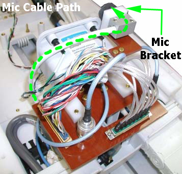
- To remove the microphone cable, pull out the silver block attached
to the end of the microphone cable from behind the microphone bracket.
Figure 4. Microphone Cable Path
- Remove the LEDs from the bezel. Be careful not to disconnect
the cable from the LEDs.
Figure 5. Removing LED from LED and Switch Harness
 note:
note:Reuse the LEDs from the old A-port bezel.
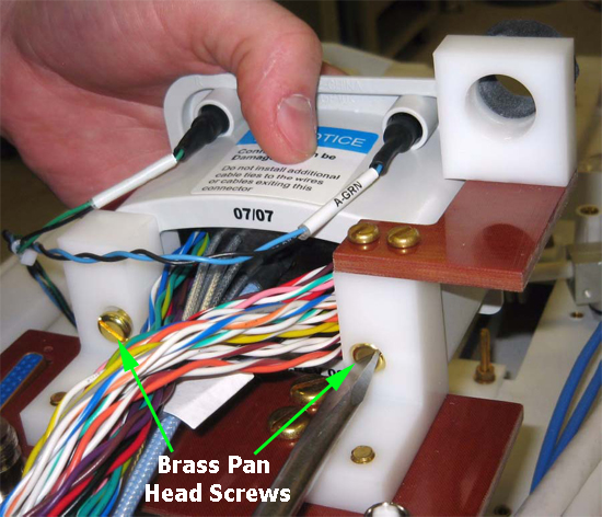
- To remove the A-port bezel from the sub-D plate, remove two
brass pan head screws (left and right) from the plate bracket at the
rear of the A-port bezel.
Figure 6. A-Port Bezel Screws
 |
Replacing A-Port Bezel
Procedure
 danger
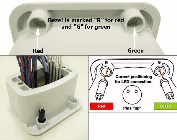
- To replace the LED into the socket of the new A-port bezel,
use a small slotted screwdriver to push the LED into place, making
sure the LED is flush with the face of the bezel.
Figure 7. A-Port Bezel LED Connections
- Attach the new bezel to the sub-D plate by replacing the brass pan head screws (left and right). See Figure 6.
- To properly reconnect all cables, do the following:
- Spread the two sections of wire on J2 and feed J1 though the
separation.
Figure 8. Bezel Cable Routing – substep a
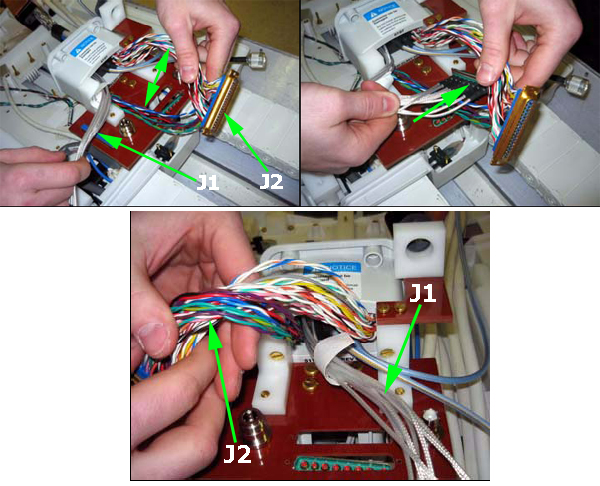
- Leave J1 lying straight out, then rotate J2 counter-clockwise
as needed until it meets up properly with J2 through the sub-D plate.
Push the two connectors together and then secure them using 3/16 inch
nuts and a 3/16 inch nut driver.
Figure 9. Bezel Cable Routing – substep b
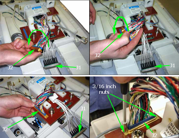
- Connect J5 to the N bulkhead adapter on the sub-D plate.
Figure 10. Bezel Cable Routing – substep c
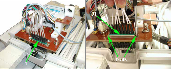
- Connect J1 to J1, through the sub-D plate. Push the two connectors
together and then secure them using 3/16 inch nuts and a 3/16 inch
nut driver.
Figure 11. Bezel Cable Routing – substep d
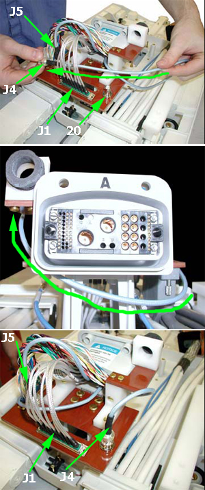
- Feed J4 between J1 and J5. Then wrap J4 around the front of
the sub-D plate, ensuring that it routes below the bezel. Connect
J4 to the BNC bulkhead adapter on the top of the sub-D plate.
Figure 12. Bezel Cable Routing – substep e
- Spread the two sections of wire on J2 and feed J1 though the
separation.
- Verify that the cables are routed and connected as shown in Figure 3.
- Replace the microphone cable into the microphone bracket. See Figure 4.
- Replace the LPCA cover (see Removing and Replacing the LPCA Cover).
 |
Removing and Replacing LED and Switch Harness
Systems using the RRx receive chain have both the LED and switch harness, and systems using the DPP receive chain only have the switch harness. Follow this procedure for both systems.
Procedure
- Remove the LPCA cover (see Removing and Replacing the LPCA Cover).
Figure 13. Front of LPCA, LED and Switch Harness Connection Points – RRx Receive Chain
-
(For RRx systems) In the middle of the LPCA
near the drive belt well, disconnect the LED and switch harness from
the cable track A connection.
(For DPP systems) In the middle of the LPCA near the drive belt wall, disconnect the switch harness from the cable track P1 connection.
-
(For RRx systems) At the rear of the LPCA, remove
the LEDs from the top of the A-port bezel. Be careful not to disconnect
the cable from the LEDs.
Figure 14. Rear of LPCA and Switch Harness Connection Points – RRx Receive Chain
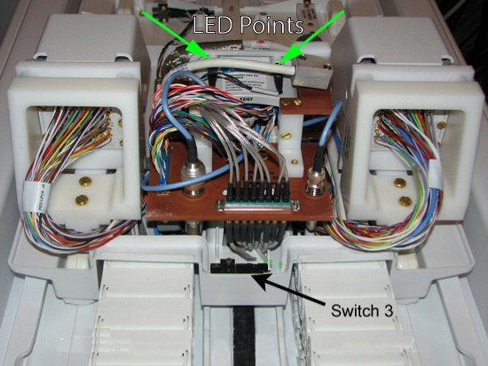
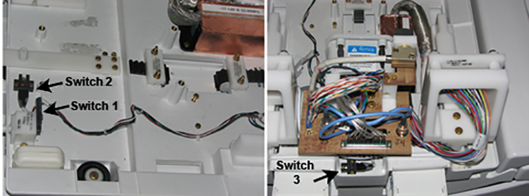
- Remove all screws holding all three switches.
Switches 1 and 2 are on the front of the LPCA, and switch 3 is in the rear of the LPCA.
Figure 15. Switch Locations
- Remove the harness.
- Replace the switches, label side visible at front and rear of the LPCA, then to the cable track A connection in the middle, and then reinstall the LEDs (if present).
- Replace the LPCA cover (see Removing and Replacing the LPCA Cover).
Removing and Replacing Cradle Latch
Procedure
- Remove the LPCA cover (see Removing and Replacing the LPCA Cover).
- Remove the four brass slotted head screws at the base of the
cradle latch.
Figure 16. LPCA Cradle Latch
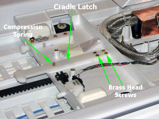
- On the bottom side of the latch, use a standard head screwdriver to remove the compression spring screw.
- To reassemble the new cradle latch:
- Replace the compression spring screw on the bottom side of the latch.
- Replace the four brass slotted head screws at the base of the cradle latch.
- Replace the LPCA cover (see Removing and Replacing the LPCA Cover).
Removing and Replacing Sub-D (or Bulkhead) Plate
The sub-D plate contains two components on systems using the RRx receive chain (the A-port bezel and the microphone) and one component on systems using the DPP receive chain (the microphone only). To replace the sub-D plate, both components and their respective cable connections must be completely removed.
Procedure
- Remove the LPCA cover (see Removing and Replacing the LPCA Cover).
-
(For DPP systems) Remove the microphone cable and plate and sub-d plate and proceed to Step 7.
-
(For RRx systems) Follow the steps as written.
-
- notice
- To remove the A-port bezel and all of its cable connections on the top of the sub-D plate, follow the procedure in Removing A-Port Bezel.note:
Removal of the adapter connections on the bottom of the sub-D plate is described later in this procedure.
- To remove the microphone cable, pull out the silver cable block from behind the microphone bracket. See Figure 4.
- After removing and setting aside the A-port bezel and its cables, remove the sub-D plate screws. See Figure 6.
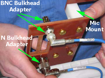
- On the bottom of the sub-D plate, remove cable connections, and then use a 16 mm non-ferrous combination wrench and a 3/4 inch non-ferrous combination wrench to remove both bulkhead adapters. See Figure 17.
- On the replacement sub-D plate, reattach cable connections and
bulkhead adapters on the bottom of the plate.
Figure 17. Bottom of Sub-D (or Bulkhead) Plate
- To reattach the sub-D plate to the LPCA assembly, do the following:
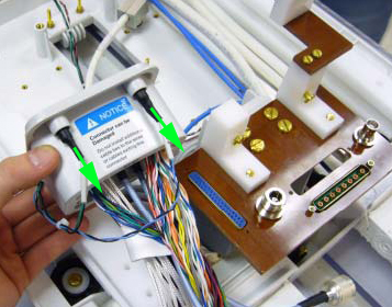
- Leave the microphone cable (silver cable block) lying straight,
making sure that it is on top of J1, J4, and J5 and not connected.
Figure 18. Reattaching Sub-D Plate and J2 Connector
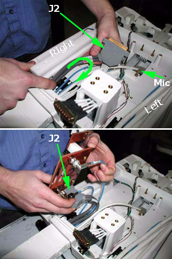
- Position J2 to the right side of the cable track and curl it until the connector is turned 180 degrees. Then locate J2 into its slot on the sub-D plate and move the plate down towards its mounting position while holding J2 in place.
- Locate the J1 connector into its slot. See Figure 3 and Figure 11.
- Reattach the four sub-D plate screws. See Figure 6.
- Leave the microphone cable (silver cable block) lying straight,
making sure that it is on top of J1, J4, and J5 and not connected.
- (For RRx systems only) To reattach the A-port bezel and its cables, see Step 3 through Step 4.
- Replace the microphone cable into the microphone bracket. See Figure 4.
- Replace the LPCA cover (see Removing and Replacing the LPCA Cover).
|
Removing and Replacing Plunger Assembly
Procedure
- Remove the LPCA cover (see Removing and Replacing the LPCA Cover).
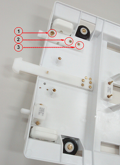
- Remove the three screws securing the plunger assembly to the
LPCA base (1,2,3) and remove the plunger assembly.
Figure 19. LPCA Plunger Assembly
- Insert replacement plunger assembly.
- Replace screws as shown in Figure 2 removed in Step 2.
- Replace the LPCA cover (see Removing and Replacing the LPCA Cover).
Finalization
Procedure
- Do a test scan to verify system operation (see Check Scan).