- id_12374920
- Version: 1.6
- Date: Nov 27, 2019 10:21:42 AM
Magnet Stud Replacement
Prerequisites
| Required persons | Preliminary requirements | Procedure | Finalization |
|---|---|---|---|
| 1 | Included in procedure | 8 hours | Included in procedure |
| Item | Quantity | Effectivity | Part number | Manufacturer |
|---|---|---|---|---|
| Wood block (for sanding) | 1 | - | - | - |
| Non-magnetic ruler | 1 | - | - | - |
| Non-magnetic tool kit | 1 | - | - | - |
| Non-ferrous safety shoes | 1 | - | - | - |
| Safety glasses | 1 | - | - | - |
| General duty gloves | 1 | - | - | - |
| DVw Stud Repair Kit | 1 | - |
5366120 |
- |
|
| Condition | Reference | Effectivity |
|---|---|---|
|
Review all safety procedures |
- | - |
|
Remove magnet enclosures and end bells covering the damaged stud. |
- | - |
Overview
This procedure describes the replacement of DVw mounting studs that are welded to the magnet. Studs that are threaded into blocks on the magnet are not included in this procedure. This procedure takes place in a magnetic field, and all safety aspects dealing with magnetic field procedures apply. The procedure you need to use depends on the location of the stud you are replacing. Table 5 shows the parts used in the procedures and where they apply.
| Part number | Part Name | Use |
|---|---|---|
| 5366178 | Stud Replacement Block, DVw Cylinder | Replacement Stud |
| 5366177 | Stud Replacement Block, DVw Flange | Replacement Stud |
| 5370258 | Spacer Isolation Stud Repair Kit | Spacer used for display panel only |
| 5370258-2 | Spacer Isolation Stud Repair Kit | Spacer used for side electronics only |
| 5368503 | Spacing Bar, For Side Electronics, Stud Replacement | Used for properly spacing studs for Side Electronics |
| U1-SVC-520047 | Sand Paper, 60 Grit, Pack of 10 | Used to remove paint on the magnet |
| 46-252065P158 | Tack Cloth, 18 x 36 inches, Trimaco SKU #10501 or Equal | Used to contain particles when sanding magnet |
| 5265376 | Dispenser, EPX Plus II, Applicator | Part of Epoxy kit |
| 46-252065P154 | Mixing Nozzle 9742, 3M Scotch-Weld EPX Applicator, 50 ml, PN 62974299356 | Part of Epoxy kit |
| 46-294151P60 or 46-294151P64 | Epoxy Henkel Loctite Metal Bonder In Duo-Pak Dispenser With Mixing Nozzle 50 ml Size. Date Code Requirement | Part of Epoxy kit |
| 5268439 | Shim, Power Connection Leadboard Axial Adjustment, XRMB Gradient | Used as spacers when replacing busbar studs (G10 washers) |
| 5214524-6 | Washer, M10 Large or Nordlock, A4 Stainless | Replacement Nordlock washers |
Cleaning Procedure for All Locations
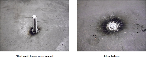
The surfaces around the broken stud on the magnet flange and the outer cylinder must be cleaned before the repair can begin. The figure below shows the area around a magnet stud.
Figure 1. Magnet Stud
Procedure
- Locate the broken stud and remove components or assemblies that attached the stud so that the broken stud and vacuum vessel surfaces around the stud are fully exposed.
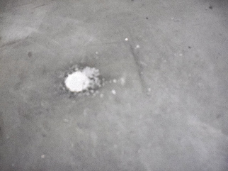
- There is usually some debris of weld and/or stud materials attached
to the vacuum vessel of magnet after the stud failure. To prevent
the debris falling into the magnet system, put a piece of tack cloth
(cloth coated with light adhesive to capture particles) underneath
the surface being cleaned to capture the falling debris. Clean the
area around broken stud with the tack cloth. After this step, the
large pieces of debris can be removed.
Figure 2. Stud Weld Area after Initial Debris Removal
- Sand off the paint on surfaces of magnet vacuum vessel using sandpaper included in the repair kit. Clean the area around broken stud with the tack cloth.
Busbar Stud Replacement
Procedure
 danger
- notice
- Perform LOTO on the PGR PDU/gradient subsystem, and the RF amplifier and PEN cabinet (magnet room electronics). See the MR Service Safety Manual, PN 5452735.
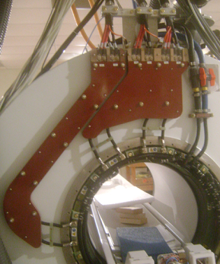
- Locate the damaged stud.
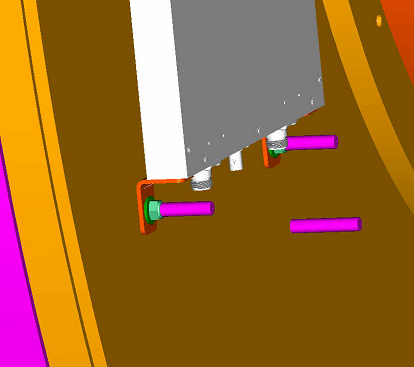
Figure 3. DVw Busbar Boards
- Remove the busbar with the damaged stud. Some studs may require the removal of both busbar boards. See XRMw Cable Busbar Replacement for these steps.
- Remove all blue washers from the remaining studs on the magnet.
- Place a total of two G10 washers (5268439) on the remaining studs on the magnet.
- Clean a 3 inch diameter area around the broken stud following the procedure in Cleaning Procedure for All Locations.
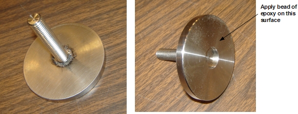
- Place a round replacement stud (5366177) into the proper location
on the busbar board. (Because the busbar board is facing downward,
the replacement stud assembly goes in stud first through the back
of the board).
Figure 4. Replacement Stud Assembly for Flanges
- Loosely attach the replacement stud assembly to the board with a G10 washer and M10 nut.
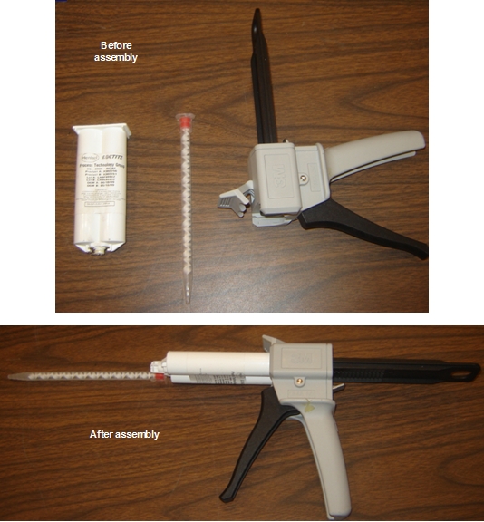
- Load an epoxy hardener cartridge into the application gun. Add
the mix nozzle to the cartridge. As the trigger is pulled, the correct
ratio of epoxy and hardener will flow out and be properly mixed in
the mixing nozzle. After mixing, the epoxy has a working life of 15
minutes.
Figure 5. Epoxy Cartridge, Mixing Nozzle, and Application Gun
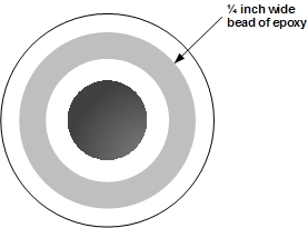
- Apply the epoxy to the mating surface of the replacement stud
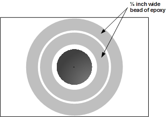
assembly. Apply a 1/4 inch circular bead of epoxy on the surface.
The center area of the mating surface is provided as a relief in case
some of the original stud could not be removed in the magnetic field.
Do not apply epoxy to this region. Epoxy may flow into this region
when it spreads later in the process.
Figure 6. Epoxy Bead Application
- Carefully position the busbar board halfway down on the remaining magnet studs.
- Press the busbar board to the magnet surface, keeping the board parallel to the magnet.
- Secure the busbar board loosely with washers and nuts.
- Remove the nut and washer from the replacement stud assembly.
- Move the replacement stud assembly around in the hole, lightly spreading the epoxy.
- Center the replacement stud in the hole.
- Tighten all of the nuts on the original studs down to slightly more than finger tight. Do not put a nut on the replacement stud.
- Wait three hours for the epoxy to cure.
- Remove the nuts and remove the busbar board.note:
Do not place G10 washers on the replacement stud. The thickness of the replacement stud base is the same as the thickness of two G10 washers.
- Add blue isolation washers back to all of the studs, including the replacement stud.
- Secure all of the busbar studs and gradient connections. See XRMw Cable Busbar Replacement.
 |
Side Electronics Stud Replacement
Procedure
- danger
- notice
- Perform LOTO on the PGR PDU/gradient subsystem, and the RF amplifier and PEN cabinet (magnet room electronics). See the MR Service Safety Manual, PN 5452735.
- Remove the side electronics components from the magnet:
-
Physiological Acquisition Controller (PAC) and Scan Room Interface (SRI-4), see Replacement of PAC and SRI-4
-
RRx Receiver (see RRx Receiver Replacement
-
Transient Detection Module (TDM), see Transient Detection Module (TDM) Replacement)
-
- Remove the side electronics plate from the magnet.
- Clean a 3 inch by 3 inch area around the stud using the procedure in Cleaning Procedure for All Locations.
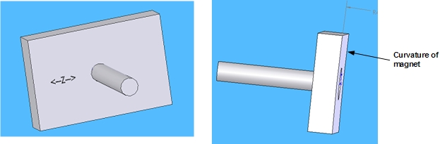
- Place the replacement stud into the spacing bar (5368503, from
Stud Repair Kit 5366120). The replacement stud assembly is made up
of a stud and 3 inch by 2 inch block. The back of the block has the
same curvature as the magnet, so the orientation of the block is critical.
The long direction of the block goes horizontally on the magnet. There
is a ←Z→ marked on the block showing
the z-direction of the magnet.
Figure 7. Replacement Stud Assembly for Side Electronics
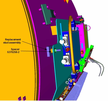
- Loosely fasten the replacement stud assembly to the bar with
G10 washers, the replacement spacer (5370258-2) and M10 nut. The replacement
stud must be located in the same position as the removed stud. The
replacement spacer is the only spacer used on the replacement stud.
The original studs reuse the original spacers.
Figure 8. Replacement Stud and Spacer
- Load the epoxy hardener cartridge into the application gun (see Figure 5). Add the mix nozzle to the cartridge. As the trigger is pulled, the correct ratio of epoxy and hardener will flow out and be properly mixed in the mixing nozzle. After mixing, the epoxy has a working life of 15 minutes.
- Apply the epoxy to the mating surface of the replacement stud
assembly. Apply two 1/4 inch circular beads of epoxy on the surface.
The center area of the mating surface is provided as a relief in case
some of the original stud could not be removed in the magnetic field.
Do not apply epoxy to this region. Epoxy may flow into this region
when it spreads.
Figure 9. Epoxy Bead Application
- Carefully position the spacing bar halfway down on the remaining magnet studs.
- After it is positioned on all of the magnet studs, press the spacing bar to the magnet surface, keeping the bar parallel to the magnet.
- Secure the spacing bar loosely with washers and nuts.
- Remove the nut and washer from the replacement stud assembly.
- Move the replacement stud assembly around in the hole, lightly spreading the epoxy.
- Center the replacement stud in the hole.
- Tighten all of the nuts on the original studs down to slightly more than finger tight. Do not put a nut on the replacement stud.
- Wait three hours for the epoxy to cure.
- Remove the nuts from the spacing bar, and remove the spacing bar.
- Replace and secure the side electronics plate.
- Replace and reconnect each of the side electronics components. Refer to:
|
Cover/Enclosure Stud Replacement
Procedure
- danger
- Perform LOTO on the PGR PDU/gradient subsystem, and the RF amplifier and PEN cabinet (magnet room electronics). See the MR Service Safety Manual, PN 5452735.
- Locate the damaged stud.
- Remove the enclosure or cover with the damaged stud. See the procedure for the component you need to remove:
- Loosen the enclosure bracket from the remaining stud.
- Clean a 3 inch by 3 inch area around the location of the broken stud using the procedure in Cleaning Procedure for All Locations.
- Place a replacement stud into the enclosure bracket. The stud
assembly is made up of a stud and a 3 inch by 2 inch block. The back
of the block has the same curvature as the magnet, so orienting the
block is critical. The long direction of the block orients horizontally
on the magnet. There is a ←Z→ marked
on the block showing the z-direction of the magnet.
Figure 10. Replacement Stud Assembly for Covers/Enclosures
- Loosely attach the replacement stud assembly to the enclosure
bracket with a G10 washer and M10 nut.
Figure 11. Replacement Stud Assembly for Covers/Enclosures
- Load the epoxy hardener cartridge into the application gun (see Figure 5). Add the mix nozzle to the cartridge. As the trigger is pulled, the correct ratio of epoxy and hardener will flow out and be properly mixed in the mixing nozzle. After mixing, the epoxy has a working life of 15 minutes.
- Apply the epoxy to the mating surface of the replacement stud
assembly. Apply two 1/4 inch circular beads of epoxy on the surface.
The center area of the mating surface is provided as a relief in case
some of the original stud could not be removed in the magnetic field.
Do not apply epoxy to this region. Epoxy may flow into this region
when it spreads.
Figure 12. Epoxy Application
- Carefully position the bracket down on the unbroken magnet stud.
- After it is positioned on the unbroken magnet stud, press the mounting bracket toward the magnet surface, keeping the bracket parallel to the magnet.
- Secure the enclosure bracket loosely with washers and nuts.
- Remove the nut and washer from the replacement stud assembly.
- Move the replacement stud assembly around in the hole, lightly spreading the epoxy.
- Center the replacement stud in the hole. Align the bracket to be parallel to the magnet flange weld (a ruler can be used for this).
- Tighten all of the nuts on the original studs down to slightly more than finger tight. Do not put a nut on the replacement stud.
- Wait three hours for the epoxy to cure.
- Remove the washer and extra nuts from the enclosure bracket.
- Replace the enclosure bracket and secure it.
- Replace the enclosures.
Body Hybrid Stud Replacement
Procedure
- notice
- Locate the damaged stud.
- Perform LOTO on the RF amplifier and PEN cabinet (magnet room electronics). See the MR Service Safety Manual, PN 5452735.
- Remove the body hybrid assembly. See Body Hybrid Replacement.
- Clean a 2 inch by 2 inch area around the broken stud using the
cleaning procedure in Cleaning Procedure for All Locations.note:
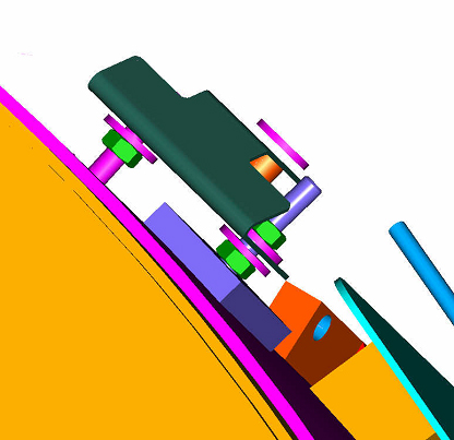
The procedure for repairing damaged body hybrid studs does not use replacement stud assemblies. Instead, epoxy is applied directly to the angle bracket screwed onto the body hybrid assembly. The figure below shows how the body hybrid assembly is normally mounted.
Figure 13. Body Hybrid Studs
- Load the epoxy hardener cartridge into the application gun (see Figure 5). Add the mix nozzle to the cartridge. As the trigger is pulled, the correct ratio of epoxy and hardener will flow out and be properly mixed in the mixing nozzle. After mixing, the epoxy has a working life of 15 minutes.
- Apply a 1/4 inch circular bead of epoxy around the hole in the bracket that attached to the broken stud. Avoid getting epoxy into the hole. Epoxy may flow into the hole when it spreads.
- Carefully position the body hybrid assembly halfway down on the remaining magnet studs.
- Press the body hybrid assembly to the magnet surface, keeping the hybrid parallel to the magnet.
- Tighten the remaining studs to slightly more than finger tight. Make sure the epoxied bracket is in full contact with the magnet surface. Loosen and adjust the epoxied bracket if necessary.
- Wait three hours for the epoxy to cure.
- Fully secure the body hybrid and reconnect electronics. See Body Hybrid Replacement.
|
Display Panel Stud Replacement
Procedure
- Locate the damaged stud.
- Perform LOTO on the PGR PDU/gradient subsystem. See the MR Service Safety Manual, PN 5452735.
- Disconnect and remove the display panel assembly.
- Clean a 3 inch diameter area around the broken stud using the cleaning procedure in Cleaning Procedure for All Locations.
- Place a replacement stud (5366177) into the display frame.
Figure 14. Replacement Stud Assembly for Flanges
- Loosely attach the replacement stud assembly to the frame with a short isolation pad (5370258), G10 washers, and M10 nut.
- Load the epoxy hardener cartridge into the application gun (see Figure 5). Add the mix nozzle to the cartridge. As the trigger is pulled, the correct ratio of epoxy and hardener will flow out and be properly mixed in the mixing nozzle. After mixing, the epoxy has a working life of 15 minutes.
- Apply the epoxy to the mating surface of the replacement stud
assembly. Apply a 1/4 inch circular bead of epoxy on the surface.
The center area of the mating surface is provided as a relief in case
some of the original stud could not be removed in the magnetic field.
Do not apply epoxy to this region. Epoxy may flow into this region
when it spreads later in the process.
Figure 15. Epoxy Bead Application
- Carefully position the display panel frame halfway down on the remaining magnet studs.
- Press the display panel frame to the magnet surface, keeping the frame parallel to the surface of the magnet.
- Secure the frame loosely with washers and nuts.
- Remove the nut and washer from the replacement stud assembly.
- Move the replacement stud assembly around in the hole, lightly spreading the epoxy.
- Center the replacement stud in the hole.
- Tighten all of the nuts on the original studs down to slightly more than finger tight. Do not put a nut on the replacement stud.
- Wait three hours for the epoxy to cure.
- Remove the nuts and reposition the display frame.
- Reinstall the display panel hardware.
Finalization
Procedure
- Reinstall all enclosures and connections.
- Perform any required system tests.