- id_15271101
- Version: 3.2
- Date: Nov 18, 2019 12:25:45 AM
Bridge and Longitudinal Drive Belt Replacement
Prerequisites
| Required persons | Preliminary requirements | Procedure | Finalization |
|---|---|---|---|
| 2 | Not Applicable | 30 to 75 minutes | 10 minutes |
| Item | Quantity | Effectivity | Part number | Manufacturer |
|---|---|---|---|---|
| Nonmagnetic Titanium Service Tool Kit, Small Set or Nonmagnetic Titanium Service Tool Kit, Large Set | 1 | - |
5113258 or 5112581 |
- |
| Item | Quantity | Effectivity | Part number | Manufacturer |
|---|---|---|---|---|
| Front Split Bridge Assembly | 1 | - |
See FRU Manual. |
- |
| Long Belt Drive | 1 | - |
See FRU Manual. |
- |
| Front Sprocket Pulley | 1 | - |
See FRU Manual. |
- |
|
Overview
This procedure explains how to replace the patient transport front split bridge, the front sprocket pulley, and the long drive belt. Plan on about 30 minutes to remove the bridge. Plan on 60 minutes if you are reinstalling the same bridge components. Plan on at least 75 minutes if you are installing a new bridge with subcomponents assembled.
Front Bridge Removal
Procedure
- Drive the LPCA and cradle into bore to within 1 ft (30 cm) of the end of the bridge.
- At the foot of the table, twist or squeeze the cradle release handle to detach the cradle from the LPCA, and then pull the cradle by hand to the home position so that it is fully retracted back onto the table top.
- Undock the table and relocate it away from the magnet.
- Follow all LOTO procedures by turning off the applicable breaker in the PDU. See the MR Service Safety Manual, PN 5452735.
- Remove the two rear pedestal covers.
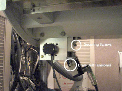
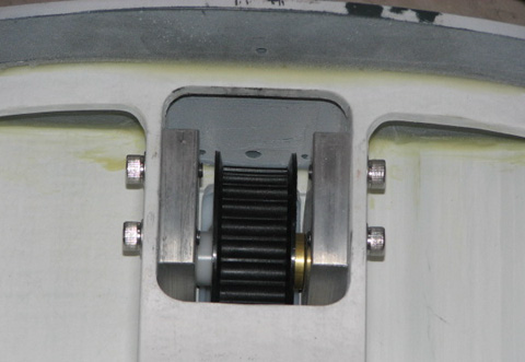
- Loosen the drive belt tensioner and the two securing screws.
Figure 1. Drive Belt Tensioner
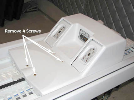
- Remove the LPCA cover by removing the four screws.
Figure 2. Location of Screws on LPCA Cover
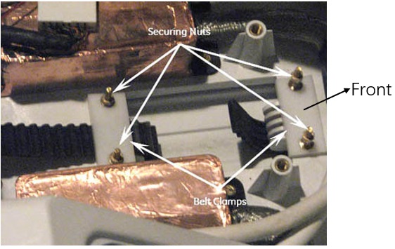
- Unscrew the two nuts on each of the two belt clamps that hold
the belt clamp plate in place.
Figure 3. Belt Clamps
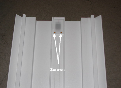
- Remove the four screws holding the belt guide cover (located
on the top rear of the rear pedestal) then remove the cover.
Figure 4. Location of Screws on Belt Guide Cover

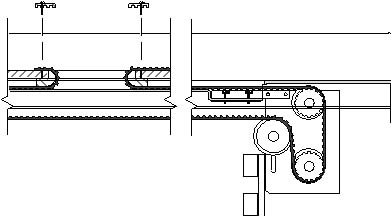
- Pull the drive belt free from the rear pedestal, and carefully
unthread the drive belt from the rear pulley.
If the same bridge is to be reinstalled, leave the drive belt on the front bridge for easier to reinstallation.
Figure 5. Drive Belt Threading Through Rear Pulley
 note:
note:To continue with bridge removal, proceed to Step 11. To remove and replace the longitudinal drive belt, proceed to Longitudinal Drive Belt (Cradle Belt) Replacement and Tension Adjustment.
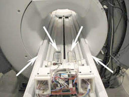
- At the rear of the split bridge, remove the four M10 nuts and
washers that attach the rear pedestal to the split bridge using a
17 mm wrench.
Figure 6. Location of Nuts at Rear of Split Bridge
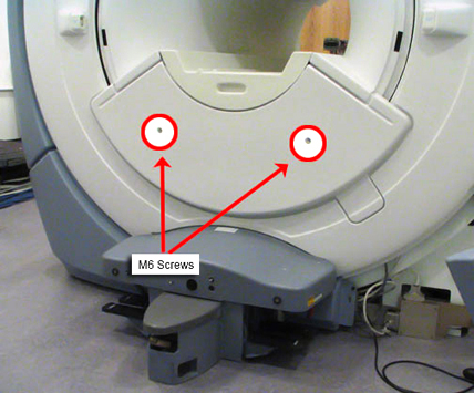
- Using a 5 mm Allen wrench, remove the two M6 screws holding
the front bridge cover in place, and remove the cover.
Figure 7. Lower Cosmetic Cover
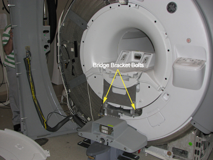
- Using a 17 mm wrench, remove the two M10 bridge bracket bolts.
When these bolts are removed, the height adjuster and spacer are no
longer secured.
Figure 8. Bridge Bracket Height Adjuster and Spacer
 caution
- Slide the bridge out from the magnet, ensuring that the drive belt comes along with the bridge. (There are wheels on the rear of the bridge for easy transport.)
 |
Replacing Bridge Part within Bridge Assembly
Procedure
- Lay the bridge on its top, and use a 5 mm Allen wrench to remove
the four M10 screws that attach the bridge mounting bracket.
Figure 9. Bridge Bracket Screw Locations
- Remove the belt from the bridge.
Figure 10. Pulley with Belt Removed
- warning
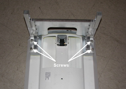
- Turn the bridge over so the top is facing up. Using a straight-blade
screwdriver, remove the two screws under the bridge top.
Figure 11. Screw Location Under Bridge Top
- Remove the pulley.
|
Bridge Installation
Procedure
- caution
- If necessary, reinstall (or newly install) the pulley ASM and drive belt onto the new bridge by reversing the steps in Replacing Bridge Part within Bridge Assembly.
- To install the bridge, reverse the steps in Front Bridge Removal.note:
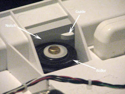
When replacing the belt, move the LPCA back on the rear bridge until the rollers extend past the notch in the guide. This allows the LPCA to be lifted for easier threading of the belt.
Figure 12. LPCA Roller
|
Longitudinal Drive Belt (Cradle Belt) Replacement and Tension Adjustment
Procedure
- Route the longitudinal drive belt.
Figure 13. Drive Belt Threading Through Rear Pulley
- Reattach belt clamps at the LPCA before reattaching the belt
guide cover at the table. With the belt tensioner fully down (no tension),
set the front belt clamp to show 3 exposed belt teeth and set the
back belt clamp to show 15 exposed belt teeth.
Figure 14. Screw Setting Tension on Cradle Belt
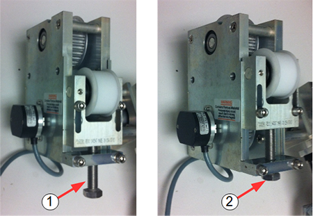
Item Description 1 Tension released 2 Tension set - Raise the belt tensioner fully to set the cradle belt tension.
- Tighten the two securing screws.
Finalization
Finalization
-
If the bridge was replaced, check for proper bridge alignment (see ).
-
Reattach the two rear pedestal covers.
-
Reattach the LPCA cover, front bridge cover, and front trim rings, and ensure a proper fit.
-
Confirm that the table top height is properly adjusted and level.
-
Perform a Check Scan to ensure that the system is functioning properly.