- id_12373477
- Version: 1.19
- Date: Jul 5, 2019 10:03:32 PM
Longitudinal Drive Motor/Encoder Replacement
Prerequisites
| Required persons | Preliminary requirements | Procedure | Finalization |
|---|---|---|---|
| 2 | Not Applicable | 30 minutes | 25 minutes |
| Item | Quantity | Effectivity | Part number | Manufacturer |
|---|---|---|---|---|
| Nonmagnetic Titanium Service Tool Kit, Large Set | 1 | - | 5112581 | - |
| Item | Quantity | Effectivity | Part number | Manufacturer |
|---|---|---|---|---|
| Longitudinal Drive Assembly | 1 | - |
See FRU Manual |
- |
|

Overview
This procedure covers the replacement of the longitudinal drive motor and encoder, which are both located on the same rear pedestal bracket assembly.
Removing Drive Motor/Encoder Bracket Assembly
Procedure
- Drive the LPCA to within 1 ft (30 cm) of the end of the rear pedestal.
- Perform LOTO on the RF amplifier and PEN cabinet (magnet room). See the MR Service Safety Manual, PN 5452735.
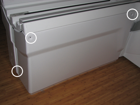
- Remove the right rear pedestal cover by removing two screws
on the right side and one rear screw. Lift up the cover out of the
bottom support brackets.
Figure 1. Rear Pedestal Screw Locations
- Remove the cover from the LPCA by removing the four screws.
Figure 2. LPCA Cover Screw Locations
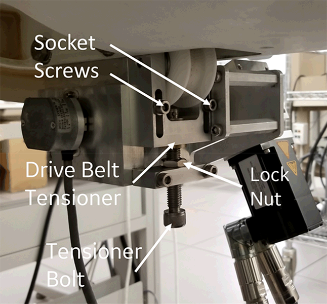
- Loosen the two socket screws on drive belt tensioner, and then
loosen the tensioner bolt until the belt becomes loose.
Figure 3. Drive Belt Tensioner
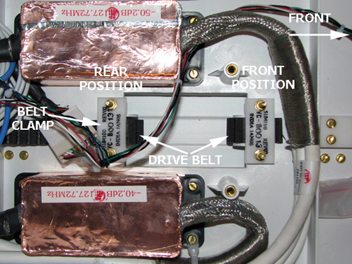
- Loosen the two nuts of the rear position belt clamp and pull
the belt out of the LPCA.
Figure 4. Belt Clamp
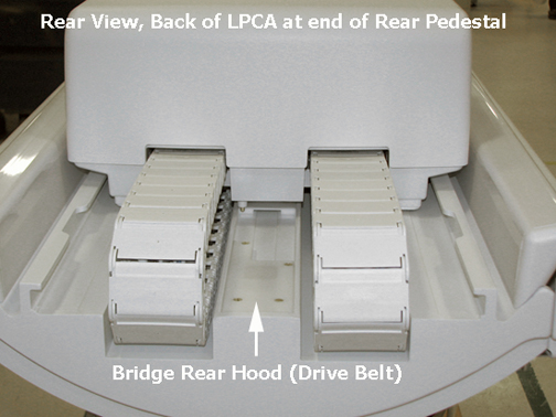
- Remove the bridge rear hood by removing the four screws.
Figure 5. Rear Pedestal Rear Hood
- Disconnect the drive motor commutator cable from the Table Interface Module (TIM) at J3, and disconnect J1 and J2 at the motor assembly.
Figure 6. Cable Path from Table Interface Module to Drive Motor/Encoder
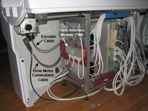 note:
note:The right pedestal cover is shown installed for picture clarity only.
- Disconnect the drive motor encoder cable from the TIM at J2.
 warning
- Loosen (do not remove) the four M10 head bolts (two on each
side) from the motor mounting bracket assembly using a 17 mm socket
wrench.note:
Have one person hold the assembly while loosening or reinstalling it to prevent cross threading.
- Carefully remove the two M10 bolts and lock-washers on one side while holding the bracket assembly in place, then remove the bolts and lock-washers on the other side. The assembly drops straight down from the bottom of the bridge. Handle with care in the magnetic field.
- Carefully maneuver the drive belt from the rear of the LPCA through the bracket assembly.
Installing Drive Motor Assembly
Procedure
- warning
- Rethread the belt through the new long drive assembly. Hold the bracket assembly in place while replacing the two M10 bolts and lock washers on each side.
- Feed the drive belt up through the bridge and into the LPCA under the belt clamp. See Longitudinal Drive Belt (Cradle Belt) Replacement and Tension Adjustment.note: Set the front belt clamp to show 3 exposed belt teeth and set the back belt clamp to show 15 exposed belt teeth.
- Tighten the tensioner bolt clockwise until the drive belt tensioner is at the top of its travel and the socket screws bottom out in the slots. Tighten the tensioner socket screws. See Figure 3.
- Replace the bridge rear hood by angling the hood onto the bridge and securing it with four brass M4 screws.
- Reattach the drive motor commutator cable to J3 and the encoder
cable to J2 on the Table Interface Module (TIM). See Figure 6
- Replace the LPCA cover with the four brass M6 pan head screws using a medium slotted screwdriver.
- Remove LOTO. See the MR Service Safety Manual, PN 5452735.
- Drive the LPCA to the front of the magnet home position.
- Replace the rear pedestal side covers.