- id_13107254
- Version: 3.0
- Date: Aug 29, 2019 1:46:06 AM
ODU Connectors Cleaning and Replacement
Prerequisites
| Required persons | Preliminary requirements | Procedure | Finalization |
|---|---|---|---|
| 1 | Not Applicable | 5 mins. per connector to clean and lubricate; 30 mins. to replace | Not Applicable |
| Item | Quantity | Effectivity | Part number | Manufacturer |
|---|---|---|---|---|
| Safety Shoes | 1 pair | - | - | - |
| Safety Glasses | 1 | - | - | - |
| 2 mm Allen Wrench | 1 | - | - | - |
| Latex-free Nitrile Gloves (8 mil) | 1 pair | - |
46-194427P400 |
- |
| Spindle Tip Replacement Tool Kit (includes blank P-port plug and T10 Torx bit driver) | 1 | - |
5150668-33 |
- |
| Item | Quantity | Effectivity | Part number | Manufacturer |
|---|---|---|---|---|
| P-Port Spindle Lubrication Kit | 1 | - |
5150668-32 |
- |
| HDv P-Port Replacement Spindle Tip Kit | 1 | - |
5150668-31 |
- |
| Cotton Swabs | As required | - | - | - |
| Soft Cloths | As required | - | - | - |
|


| Condition | Reference | Effectivity |
|---|---|---|
|
Order the lubricant kit prior to starting this procedure. |
- | - |
ODU Connector Cleaning
The P-Port receptacle must be cleaned and lubricated on each of the system P-ports (P1 and P2 on the LPCA and P3 and P4 on the 32-channel table). Also, the coil connector must be cleaned and tested for proper fit to each P-port receptacle.
Procedure
- notice
- Use the cotton swabs included in the P-Port Spindle Lubrication
Kit to clean the spindle tip on the coil connector of each coil on
site, removing all dirty lubricant and dust particles from the spindle
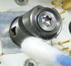
tip, especially from the groove. (See the illustrations below.)
Figure 1. Cleaning Spindle Tip
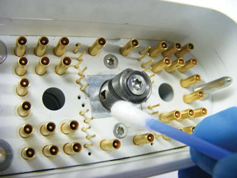
Figure 2. Cleaning Spindle Tip Groove
- notice
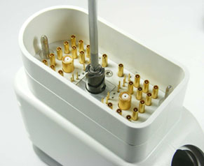
- Clean and lubricate all the system P-port connectors as shown
below.note:
Special lubricant (included in the P-Port Spindle Lubrication Kit) and cotton swabs are required for cleaning and lubricating the P-port receptacle on the scanner.
Figure 3. Cleaning P-Port Receptacle with Cotton Swab
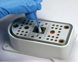
Figure 4. Lubricating with Special Syringe
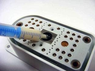
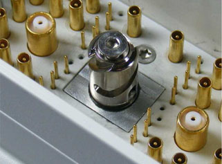
Figure 5. Location of Pins in P-Port Receptacle
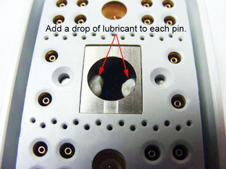
- During the cleaning process, inspect the receptacle contact surface and remove any debris.
- After all the P-Port connectors are cleaned and lubricated, cap and store the syringe with any unused portion in the original labeled packaging for future use. Assure the outer packaging is clean of lubricant, remove the protective gloves, and wash your hands to remove any lubricant residue.
- Cap and store the syringe with any unused portion in the original labeled packaging for future use.
- After the syringe is empty or has an expired date code, dispose of the syringe according to the SDS provided with the kit.
 |
|
Coil Plug Connector Spindle Replacement
Follow this procedure to replace the spindle tip on the DVMR coil connector.
Procedure
- notice
- Move the coil with the defective spindle to a suitable location outside of the Magnet Room.
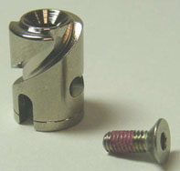
- Confirm that all components (shown below) are included in the
HDv P-Port Replacement Spindle Tip Kit.note:
Counter Sunk Screw is 8 mm long and has a red coating. A hexagonal socket is required.
Figure 6. Spindle Tip and M3 Counter Sunk Screw
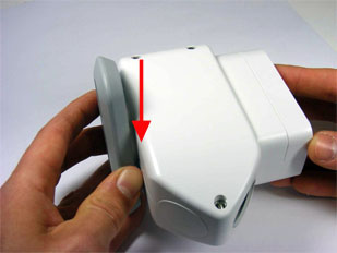
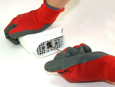
- Place the unpopulated connector found in Spindle Tip Replacement
Tool kit (5150668-33) into the coil plug connector, and rotate the
handle clockwise to lock the position as shown.
Figure 7. Placing Unpopulated Connector into Plug
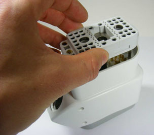
Figure 8. Rotating Unpopulated Connector to Lock in Position
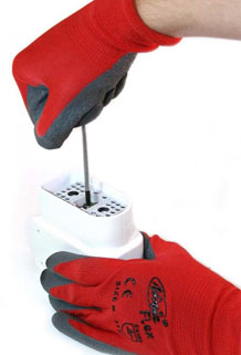
- Using the T10 Torx or a 2 mm Allen wrench, loosen the screw
on the unpopulated connector (as shown) with only one rotation counterclockwise.
Figure 9. Loosening Screw on Unpopulated Connector
- Remove the unpopulated connector from the coil plug connector.
- Loosen and remove the screw from the plug using either the T10
Torx or a 2 mm Allen wrench as shown. Discard the screw.note:
The screw from the plug must not be reused. If the screw is reused, it may loosen and the spindle may fall off.
Figure 10. Removing Screw from Plug
- Replace the spindle tip and the counter sunk screw, and turn
the screw using a 2 mm Allen wrench, but do not tighten.
Figure 11. Spindle Tip and Screw Replaced
- Place the unpopulated connector into the plug again, and rotate the handle clockwise into the locked position as shown in Figure 7 and Figure 8.
- Hand tighten the screw, and turn it an additional 1/10 turn
(1.24 Nm) with the 2 mm Allen wrench as shown.
Figure 12. Tightening Screw in Unpopulated Connector
- Remove the blank P-port plug, and save the plug and Torx bit driver for future use.
- Dispose of the removed parts according to the SDS provided with the parts kit.
|
Finalization
Finalization
-
Verify that all of the customer’s coils connect properly to all of the customer's system-side connectors.
-
If you replaced a spindle, run the appropriate MCQA test for the repaired coil.