
- SIGNA MR355 / SIGNA MR360
- Service Manual
- 5856356-3EN Revision 5.0
- Basic Service Documentation. Copyright General Electric Company.
- 00000018WIA30142030GYZ
- id_131064951.4
- Jul 5, 2019 10:25:10 PM
XFA
Prerequisites
| Required persons | Preliminary requirements | Procedure | Finalization |
|---|---|---|---|
| 1 | Not Applicable | 90 minutes | 35 minutes |
| Item | Quantity | Effectivity | Part number | Manufacturer |
|---|---|---|---|---|
| Standard Tool | 1 | - | - | - |
| Ladder | 1 | - | - | - |
| Fixed Site Lift Tool Kit | 1 | - |
46-317266 All Generation | - |
| Item | Quantity | Effectivity | Part number | Manufacturer |
|---|---|---|---|---|
| XFA (Refer to Illustrated Parts) | 1 | - | - | - |
| ||||||||||||||||
| Condition | Reference | Effectivity |
|---|---|---|
|
System Power must be turned OFF. Refer to Lockout / Tagout for MDP(Main Disconnect Panel) or Facility PDU . | - | - |
Procedure
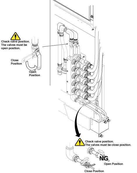
Disconnect the IN and OUT quick couplers of XFA X, Y or Z from the water manifold.Warning Figure 1. Water Manifold Socket Order 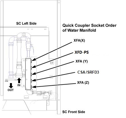
Connect the IN and OUT of quick coupler, and tie the hose as illustration.CAUTION Figure 2. Water Manifold 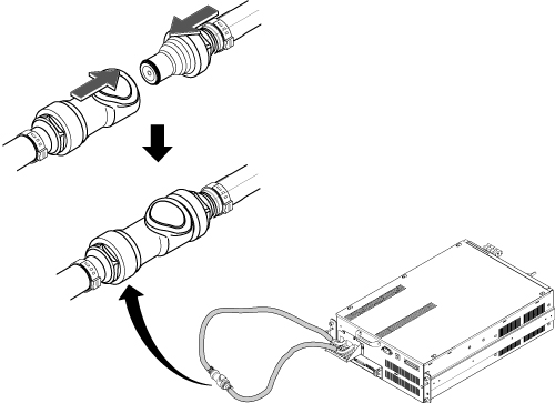
- Remove the cabinet leak sensor assy by loosening 6 screws.
Figure 3. Remove Leak Sensor 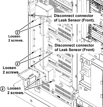
- Loosen 4 screws tightening XFA front panel to the chassis.
Figure 4. Terminal Cover Removal and Loosening 4 Screws 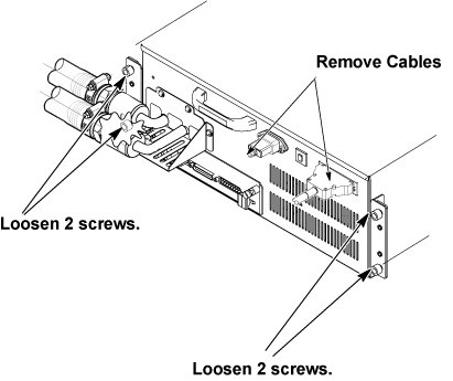
- Screw two M5 (40mm) screws at the two screw holes to push the
XFA to the chassis and gradually slide it out from Cabinet.
Figure 5. Gradually Slide Out Using Screws 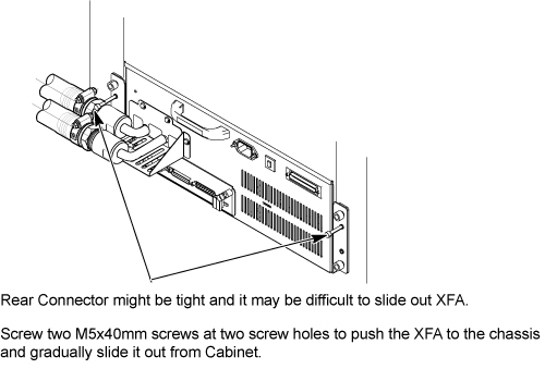 Note:
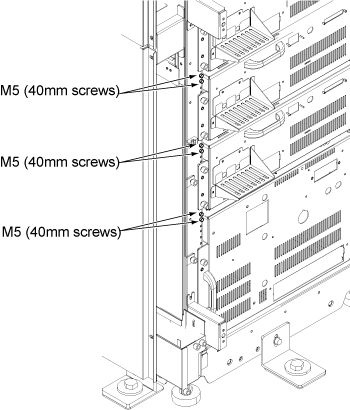
Note:M5 Screws to push out XFA are located at chassis as following illustration
 Note:
Note:If you cannot withdraw XFA using M5 screw, need to disconnect connector from rear side. Refer to In case connector of XFA or XFD-PS is very tight.
- Install the hoist brackets to the chassis of XFA with 4 screws.
Do not tighten 4 screws of hoist brackets.Note:
Hoist Bracket is stored in FRU box.
Figure 6. Hoist Brackets Installation 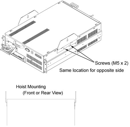
- Press the release tabs in on each side as you pull the unit
out further.
Figure 7. Hoist Operation 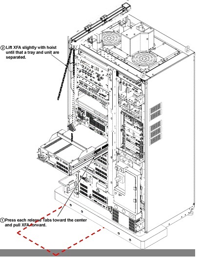
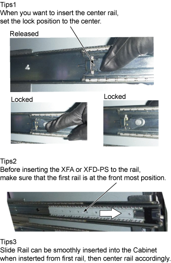
Push the rail slider into the system cabinet before lowering XFA.Notice Note:Here is the tips of slider rail operation.
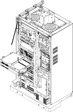
- Use the hoist and slowly lower the XFA Chassis to the floor.Note:
When lowering the XFA Chassis, it may be easier to rotate XFA 90 degree as following illustration.
- Install XFA by the reverse order of the removal.Note:
Make sure to connect all cables and hoses.
Note:Make sure to close draining valves and open Supply and Return valves.
Finalization
Procedure
- Restore the Power. Refer to Lockout / Tagout for MDP(Main Disconnect Panel) or Facility PDU .
- Refill Coolant. Refer to Refill Coolant after replacement of SRFD3, XFA, or XFD-PS.
- To adjust DC Offsets, refer to DC Offset Adjustment.
- Perform [TPS Reset].
- Perform DQA Tool.
- Perform Signal to Noise - Head Scan.