
- SIGNA MR355 / SIGNA MR360
- Service Manual
- 5856356-3EN Revision 5.0
- Basic Service Documentation. Copyright General Electric Company.
- 00000018WIA303CEF20GYZ
- id_131065691.5
- Jan 31, 2021 9:23:57 PM
Draining Operation before replacing CSA/SRFD3, XFA, XFD-PS
Prerequisites
| Required persons | Preliminary requirements | Procedure | Finalization |
|---|---|---|---|
| 1 | Not Applicable | 30 minutes | Not Applicable |
| Item | Quantity | Effectivity | Part number | Manufacturer |
|---|---|---|---|---|
| Coolant Tank (Attached in System Cabinet) | 1 | - | - | - |
| Water tray (Attached in System Cabinet) | 1 | - | - | - |
| Hand Pump (Attached in System Cabinet) | 1 | - | - | - |
| ||||
| Condition | Reference | Effectivity |
|---|---|---|
|
System Main Breaker is OFF. Refer to System Cabinet PDU Main Breaker LOTO Procedure. | - | - |
Procedure
- Set the drain hoses to the equipped coolant tank. See Figure 3. (The opening
of equipped coolant tank is a little bit small for two drain hoses.
But, it is possible to insert two hoses.)Note:
The Equipped Coolant Tank is found in the drip pan of SC left side.
Note:The water tray and hand pump are found in the under side of cabinet monitor.
Figure 1. Location of Coolant Tank 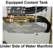
Figure 2. Location of Water tray, and Hand Pump 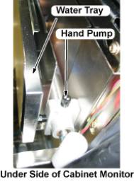
Open the drain valves. See Figure 3.Notice Figure 3. Open Drain Valve 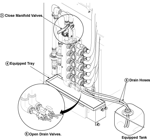
-
Figure 4. Setup and push out coolant 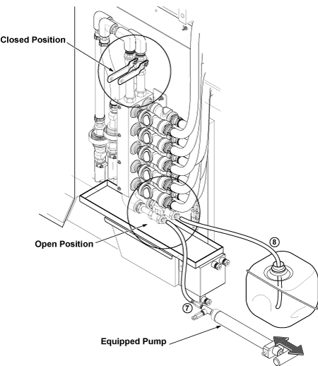
- Close drain valves surely.
Figure 5. Close Drain Valve 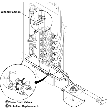
- Go to CSA/SRFD3, XFA, or XFD-PS unit replacement.
Figure 6. Water Manifold Socket Order 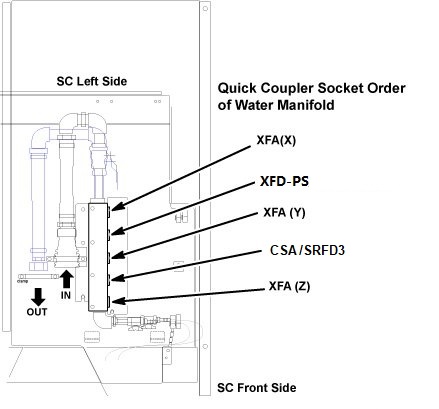
Finalization
- After Replacement is done, make sure to close draining valves
and open Supply and Return valves.
Figure 7. Restoration 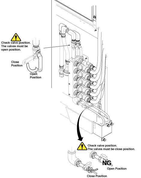
- Restore Water Tray and Coolant Tank.
- Restore draining hoses as it was.
- Connect sensor cables which are disconnected in Step 4.
- Restore Covers.