
- SIGNA MR355 / SIGNA MR360
- Service Manual
- 5856356-3EN Revision 5.0
- Basic Service Documentation. Copyright General Electric Company.
- 00000018WIA303A0030GYZ
- id_131062831.1
- Jul 5, 2019 10:46:04 PM
HUB Replacement in System Cabinet
Prerequisites
| Required persons | Preliminary requirements | Procedure | Finalization |
|---|---|---|---|
| 1 | Not Applicable | 30 minutes | 15 minutes |
| Item | Quantity | Effectivity | Part number | Manufacturer |
|---|---|---|---|---|
| Standard Tool | 1 | - | - | - |
| Item | Quantity | Effectivity | Part number | Manufacturer |
|---|---|---|---|---|
| Ethernet Switch (FRU Manual) | 1 | - |
Refer to FRU Manual | - |
Note:
The unit can be withdrawn with slide rail. | ||||
| Condition | Reference | Effectivity |
|---|---|---|
|
System Power must be turned OFF. Refer to System Cabinet PDU Main Breaker LOTO Procedure. | - | - |
About this task
Procedure
- Perform the following steps.
- Disconnect all connectors from front of HUB.
- Remove 2 screws.
- Slide out the tray.
- Disconnect power cable.
- Peel Velcro tape and remove HUB.
The HUB is located beside the ICE, above the DCPS for ICE.
Figure 1. HUB location in SC 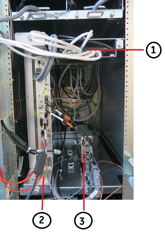
(1) HUB (3) DCPS for ICE (2) ICE Figure 2. HUB Removal 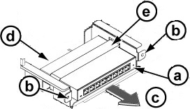
Finalization
- Restore the Power. Refer to System Cabinet PDU Main Breaker LOTO Procedure.
- Open C Shell and type as follows. Check that result of each
ping test is OK.
- ping agp [Enter]
- ping scp [Enter]
- ping vre [Enter]
- Perform SPT Head SNR Check.