
- SIGNA MR355 / SIGNA MR360
- Service Manual
- 5856356-3EN Revision 5.0
- Basic Service Documentation. Copyright General Electric Company.
- 00000018WIA302EEF20GYZ
- id_131069761.1
- Jul 5, 2019 10:46:04 PM
In case connector of XFA or XFD-PS is very tight
Prerequisites
| Required persons | Preliminary requirements | Procedure | Finalization |
|---|---|---|---|
| 1 | Not Applicable | 60 minutes | Not Applicable |
| Item | Quantity | Effectivity | Part number | Manufacturer |
|---|---|---|---|---|
| Non Magnetic Tool Set | 1 | - | - | - |
| Digital volt meter (DVM) | 1 | - | - | - |
| Item | Quantity | Effectivity | Part number | Manufacturer |
|---|---|---|---|---|
| - | - | - | - |
| ||||||||
| Condition | Reference | Effectivity |
|---|---|---|
|
PDU must be turned OFF. Refer to Lockout / Tagout for MDP(Main Disconnect Panel) or Facility PDU. | - | - |
Procedure
- Turn the SW1 to Discharge on front of XFD-PS if not done.
Figure 1. Discharge 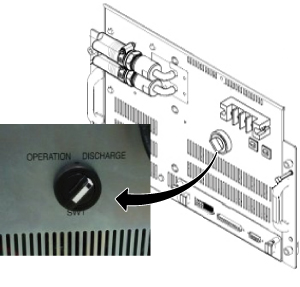
Wait for 30 minutes.CAUTION 
- Remove Cover for XFD Power Pannel Assy.
Figure 2. Cover for XFD Power Pannel Assy. 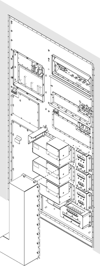
- Check the voltage at each axis terminals (X, Y, Z) and confirm
that there is no voltage. Refer to Figure 3 for voltage
check point.Note:
Normally, the voltage of upper terminal will be 0 V after 30 minutes.
For lower terminal, the voltage may exist in case of switch failure in XFD-PS and the charge of super capacitor cannot be discharged.
If voltage exists in lower terminal, please check that SW1 of XFD-PS is turned to discharge position.
If SW1 is at discharge position, waited for 30 minutes, and voltage still exists at lower terminal, wait until the voltage becomes 0V.
While waiting, please install cover for XFD Power Pannel Assy.
At worst case, it will take 1 days to discharge.
Figure 3. Voltage Check 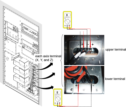
Finalization
- Once XFA or XFD-PS is installed, connect the connector of XFD Power Pannel Assy and fix the screw tightly.
- Install Cover for XFD Power Pannel Assy.
- For normal operation, do not forget to turn the SW1 of XFD-PS to OPERATION mode.