
- SIGNA MR355 / SIGNA MR360
- Service Manual
- 5856356-3EN Revision 5.0
- Basic Service Documentation. Copyright General Electric Company.
- 00000018WIA3078FF20GYZ
- id_131063211.3
- Jul 5, 2019 11:18:59 PM
CSA
Prerequisites
| Required persons | Preliminary requirements | Procedure | Finalization |
|---|---|---|---|
| 1 | Not Applicable | 45 minutes | 90 minutes |
| Item | Quantity | Effectivity | Part number | Manufacturer |
|---|---|---|---|---|
| Standard Tool | 1 | - | - | - |
| Ladder | 1 | - | - | - |
| Fixed Site Lift Tool Kit | 1 | - |
46-317266 All Generation | - |
| Item | Quantity | Effectivity | Part number | Manufacturer |
|---|---|---|---|---|
| CSA (Refer to Illustrated Parts) | 1 | - | - | - |
| ||||||||||||||||
| Condition | Reference | Effectivity |
|---|---|---|
|
System Power must be turned OFF. Refer to System Cabinet PDU Main Breaker LOTO Procedure. | - | - |
About this task
Procedure
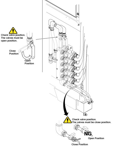
Disconnect the IN and OUT quick couplers of CSA from the water manifold.Warning Figure 1. Water Manifold Socket Order 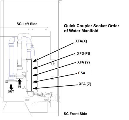
Connect the IN and OUT quick couplers of CSA, and tie the hose as illustration.CAUTION Figure 2. Water Manifold 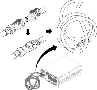
- Remove the cabinet leak sensor assy by loosening 6 screws.
Figure 3. Remove Leak Sensor Assy 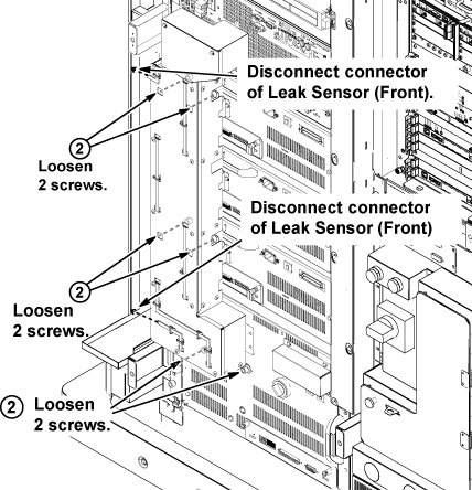
- On the front of the ICN, remove the three screws and remove
ICN Noise Duct.
Figure 4. Remove ICN Noise Duct 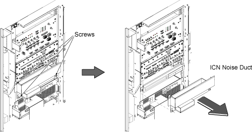
- Withdraw CSA from the chassis until it stops at stopper position
of slider rail.
Figure 5. Withdraw CSA 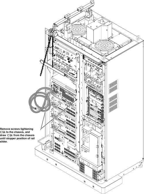
- Install the hoist assembly to the hoist brackets of CSA, and
tighten 6 screws of hoist brackets. Check that hoist bracket and hoist
assembly are installed surely.
Figure 6. Attach Hoist Bracket 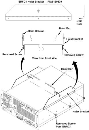
- Insert the tray into the chassis completely.
Figure 7. Hoist Operation 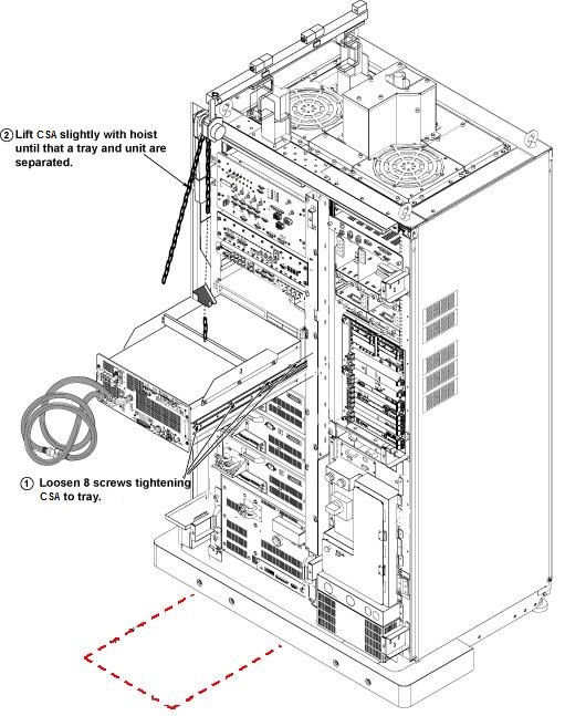
Use the hoist and slowly lower the CSA Chassis to the floor. Remove the two hoist brackets from CSA chassis.Notice Figure 8. Hoist Operation 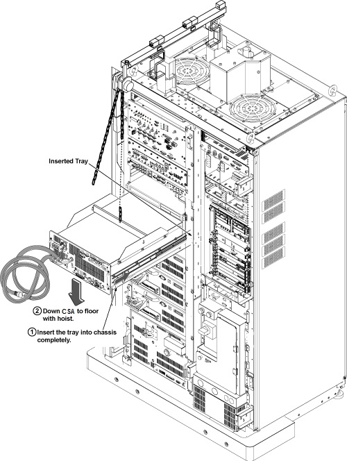
- Install CSA by the reverse order of the removal.Note:
Make sure to connect all cables and hoses.
Note:Make sure to close draining valves and open Supply and Return valves.
Finalization
- Restore the Power. Refer to System Cabinet PDU Main Breaker LOTO Procedure.
- Refill Coolant. Refer to Refill Coolant after replacement of CSA, XFA, or XFD-PS.
- Perform RF Output Power Check. Refer to Body and Head Maximum Power Setup and Calibration.
- Perform UPM Functional Check. Refer to UPM- Body and Head Functional Check .
- Perform Signal to Noise - Head Scan.