
- SIGNA MR355 / SIGNA MR360
- Service Manual
- 5856356-3EN Revision 5.0
- Basic Service Documentation. Copyright General Electric Company.
- 00000018WIA3039FF20GYZ
- id_131072611.2
- Jul 5, 2019 10:46:05 PM
Hoist Setup
Prerequisites
| Required persons | Preliminary requirements | Procedure | Finalization |
|---|---|---|---|
| 1 | Not Applicable | 30 minutes | Not Applicable |
| Item | Quantity | Effectivity | Part number | Manufacturer |
|---|---|---|---|---|
| Fixed Site Lift Tool Kit | 1 | - |
46-317266 All Generation | - |
| ||||||||
Procedure
- Remove L top cover by loosening 10 screws.
Figure 1. Rear Hoist Base and L TOP Cover Removal 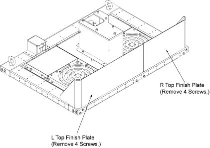
- Remove Support Bracket assembly on the top of the cabinet top
plate of System Cabinet by removing 4 screws (M6x25).
Figure 2. Remove Support Bracket assembly 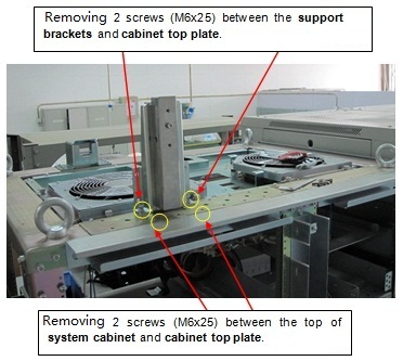
- Set up Hoist tool. De-assembly Support Brackets by removing
3 screws.
Figure 3. De-assembly Support Brackets 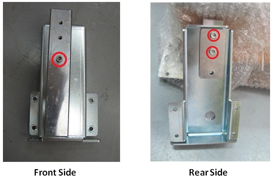
Figure 4. Remove 3 screws 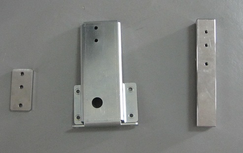
- Fix the bigger Bracket on the top of System Cabinet by fixing
4 screws.
Figure 5. After Remove Support Bracket assembly 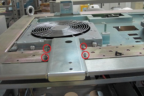
- Locate the three (3) large Steel Rail sections and place them
on a flat surface for assembly.
Figure 6. three large Steel Rail 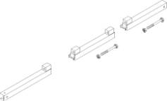
- Fix Rail and Brackets by fixing 3 screws
Figure 7. Fix Rail and Brackets 1 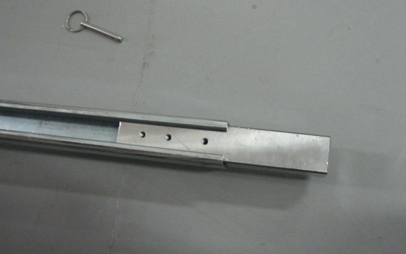
Figure 8. Fix Rail and Brackets 2 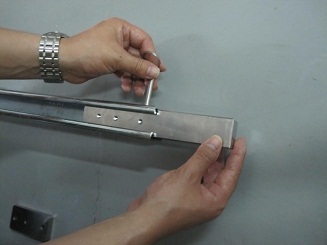
Figure 9. Fix Rail and Brackets 3 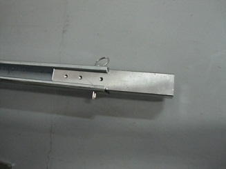
Figure 10. Fix Rail and Brackets 4 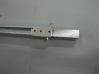
Figure 11. Fix Rail and Brackets 5 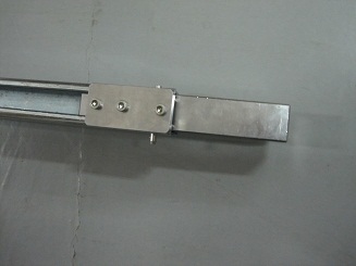
- Put large steel rail on the top of the System Cabinet and insert
it bracket.
Figure 12. three large Steel Rail 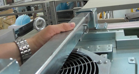
- Fixing another bracket and rail by 2 screws.
Figure 13. Bracket from hosit tool 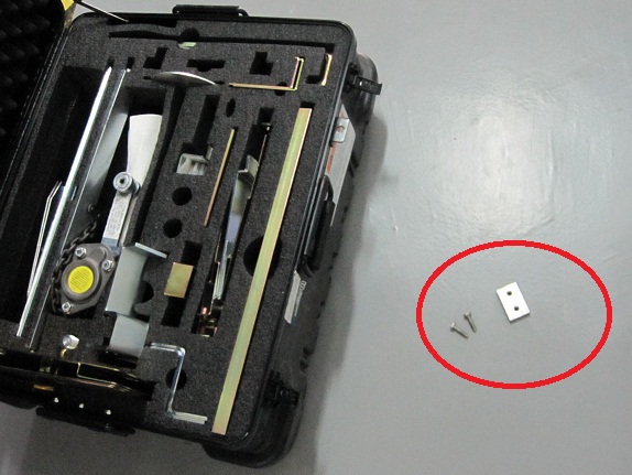
Figure 14. Installation Bracket 1 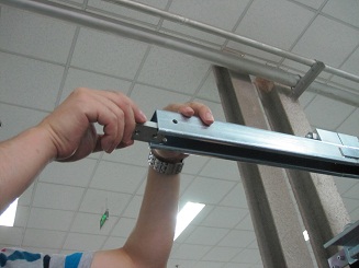
Figure 15. Installation Bracket 2 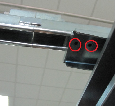 Note:
Note:Make sure that two yellow screws are tighten.
Figure 16. Installation Bracket 3 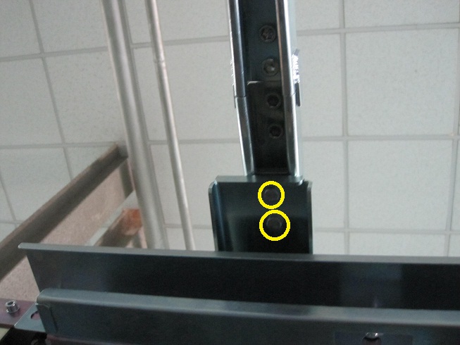
- Locate the hoist assembly in the lift kit.
Figure 17. hoist assembly 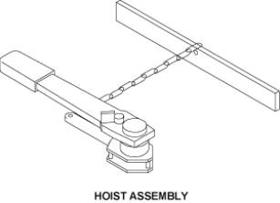
- Insert the hoist assembly into the front end of hoist rail,
and then insert a locking pin into the hole of front rail. This locking
pin prevents the hoist assembly from sliding out of the rail.
Figure 18. Insert the hoist assembly and lock 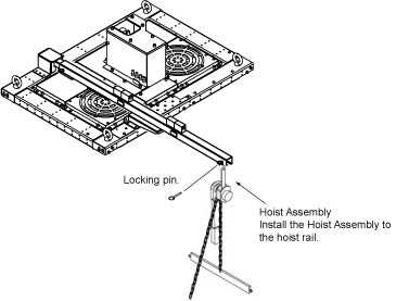
Finalization
- After replacement is completed, restore it by reverse order.