
- SIGNA MR355 / SIGNA MR360
- Service Manual
- 5856356-3EN Revision 5.0
- Basic Service Documentation. Copyright General Electric Company.
- 00000018WIA30432030GYZ
- id_131060901.3
- Jul 5, 2019 10:46:04 PM
Water Manifold
Prerequisites
| Required persons | Preliminary requirements | Procedure | Finalization |
|---|---|---|---|
| 1 | Not Applicable | 60 minutes | Not Applicable |
| Item | Quantity | Effectivity | Part number | Manufacturer |
|---|---|---|---|---|
| Coolant Tank (Attached in System Cabinet) | 1 | - | - | - |
| Water tray (Attached in System Cabinet) | 1 | - | - | - |
| Hand Pump (Attached in System Cabinet) | 1 | - | - | - |
| Phillips Driver | 1 | - | - | - |
| Standard Tool | 1 | - | - | - |
| Item | Quantity | Effectivity | Part number | Manufacturer |
|---|---|---|---|---|
| Water Manifold | 1 | - | - | - |
| ||||
| Condition | Reference | Effectivity |
|---|---|---|
|
System Main Breaker is OFF. Refer to System Cabinet PDU Main Breaker LOTO Procedure. | - | - |
Procedure
- Close the Manifold Valves.
Figure 1. Water Manifold Access Cover and Manifold Valves 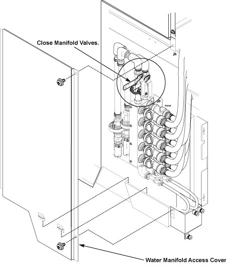
- Set the drain hoses to the equipped coolant tank.Note:
The Equipped Coolant Tank is found in the drip pan of SC left side.
Note:The water tray is found in SC Left shelf under cabinet monitor.
Figure 2. Location of Coolant Tank, Water tray, and Hand Pump 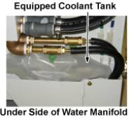
- Remove the hose clamps by removing 4 nuts and disconnect the
IN/OUT hoses from the water manifold.
Figure 3. Disconnect Hoses and Draining Setting 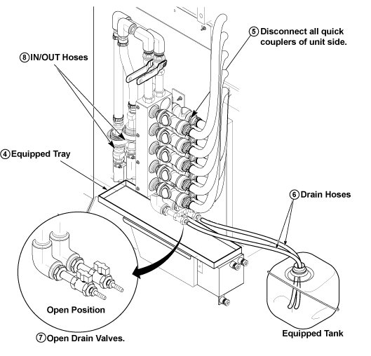
- Withdraw the water manifold assy from SC.
Figure 4. Push Out Coolant 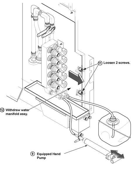
- Remove the water manifold assy by removing 3nuts with 10 mm
wrench.
Figure 5. Water Manifold Removal 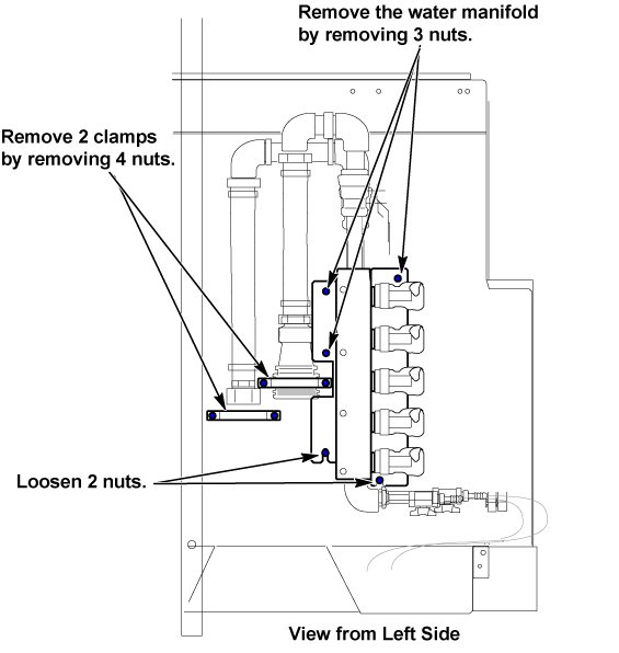
Finalization
About this task
| Notice | |
|---|---|
Procedure
- Restore the Power. Refer to System Cabinet PDU Main Breaker LOTO Procedure.
- Check that there is not a water leak from the water manifold.
- Perform Signal to Noise - Head Scan.