
- SIGNA MR355 / SIGNA MR360
- Service Manual
- 5856356-3EN Revision 5.0
- Basic Service Documentation. Copyright General Electric Company.
- 00000018WIA30F42030GYZ
- id_131058251.3
- Jul 6, 2019 12:17:32 AM
XFD-PS Replacement (Mobile Site)
Prerequisites
| Required persons | Preliminary requirements | Procedure | Finalization |
|---|---|---|---|
| 1 | Not Applicable | 120 minutes | 15 minutes |
| Item | Quantity | Effectivity | Part number | Manufacturer |
|---|---|---|---|---|
| Standard Tool | 1 | - | - | - |
| Ladder | 1 | - | - | - |
| Fixed Site Lift Tool Kit | 1 | - |
46-317266 All Generation | - |
| Item | Quantity | Effectivity | Part number | Manufacturer |
|---|---|---|---|---|
| XFD-PS (Refer to Illustrated Parts) | 1 | - | - | - |
| ||||||||||||
| Condition | Reference | Effectivity |
|---|---|---|
|
System Power must be turned OFF. Refer to Lockout / Tagout for MDP(Main Disconnect Panel) or Facility PDU. | - | - |
Remove XFD-PS
Procedure
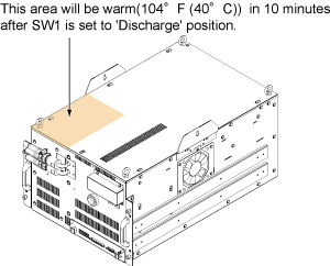
Turn the SW1 to Discharge on Front .Notice Figure 1. Discharge 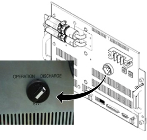
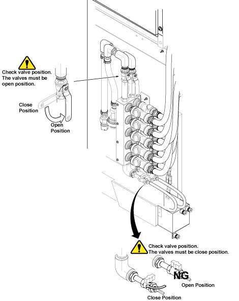
Disconnect the IN and OUT quick couplers of XFD-PS from the water manifold.Warning Figure 2. Water Manifold Socket Order 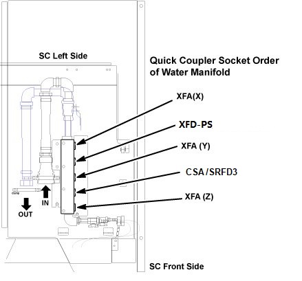 Note: When disconnecting the quick couplers, move the couplers in parallel not to damage it.
Connect the IN and OUT of quick coupler.CAUTION Figure 3. Water Manifold 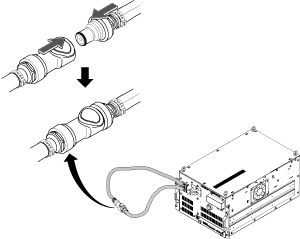
- Remove the cabinet leak sensor assy by loosening 6 screws.
Figure 4. Remove Leak Sensor 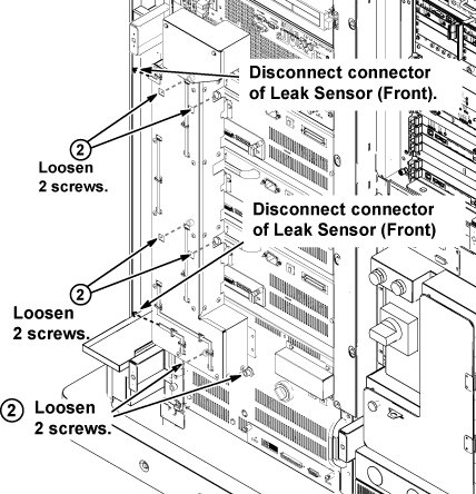
- Loosen 4 screws which are tightening XFD-PS front panel to
the chassis.
Figure 5. Remove Terminal Cover 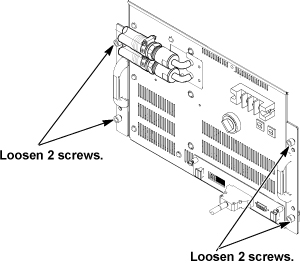
- Note:Screw two M5 (40mm) screws at the two screw holes to push the XFD-PS to the chassis and gradually slide it out from Cabinet.
M5 Screws to push out XFD-PS are located at chassis as following illustration.
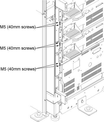
Figure 6. Gradually Slide Out Using Screws 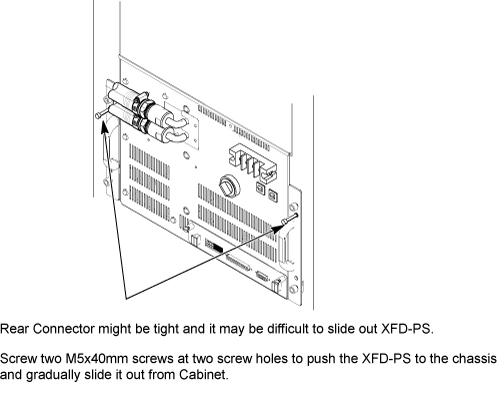 Note: If you cannot withdraw XFD-PS using M5 screw, need to disconnect connector from rear side. Refer to In case connector of XFA or XFD-PS is very tight.
Install hoist brackets to the chassis of XFD-PS with 4 screws. Do not tighten 4 screws of hoist brackets.Notice Note: Hoist Bracket is stored in FRU box.Figure 7. Hoist Brackets Installation 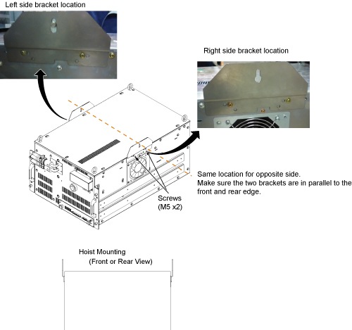
- Press the release tabs in on each side as you pull the unit
out further.
Figure 8. Hoist Operation of XFD-PS 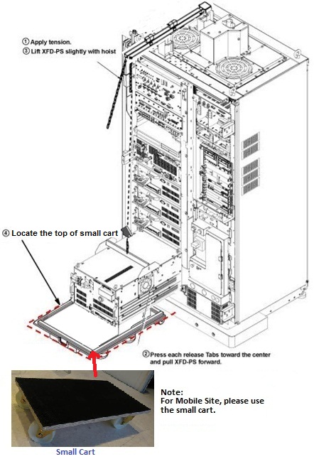
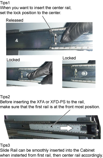
Push the rail slider into the system cabinet before lowering XFD-PS.Notice Note:Here is the tips of slider rail operation.
Lift the XFD-PS up slightly to place the top of the small cart.CAUTION 
- Check that no LED is lit from the slit of right panel. If any
LED is lit, Switch may be in failure and there exists charge inside
of XFD-PS.
Figure 9. LED Check 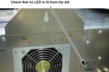
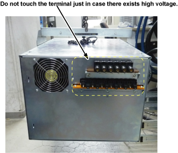
If LED is lit, check the voltage of rear terminal. See Figure 10.
Figure 10. Rear View of XFD-PS 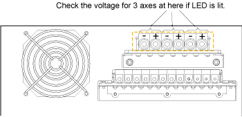
If voltage exist, wait until LED is turned OFF before transferring defective XFD-PS.
At worst case, it will take 1 days to discharge.
Note: EDLC (Super Capacitor in XFD-PS) is safe during discharge state unless the terminal is shorted.Note: Never short the terminal of XFD-PS. - Install the hoist tool to the hoist point of trailer
Figure 11. Install the hoist tool to the hoist point of trailer 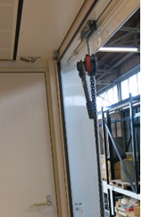
- Hoist the PS from the hoist point of trailer and put onto the
top cover of PS FRU package.
Figure 12. Put XFD-PS to the top of FRU package 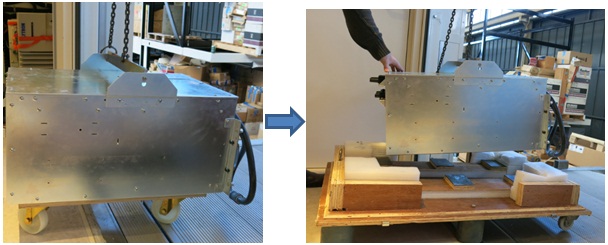
- Uplift and move the PS with package out of the trailer.
Figure 13. Move the PS with package out of the trailer 
Install XFD-PS (Mobile Site)
Procedure
- Hoist the XFD-PS from the hoist point of trailer.
Figure 14. Hoist XFD-PS 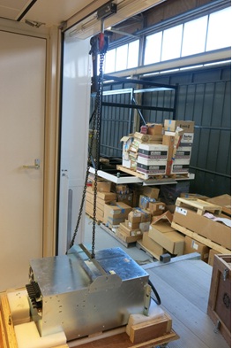
- Put the XFD-PS onto the small cart in the operating room.
Figure 15. Put XFD-PS to small cart 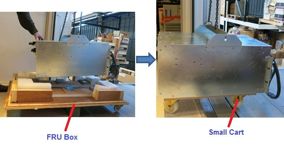
- Move the cart with new XFD-PS to the equipment room
Figure 16. Move new XFD-PS to the equipment room 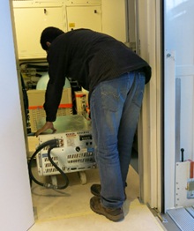
- Install XFD-PS by the reverse order of the removal. Note: Make sure to connect all cables and hoses.Note: Make sure to close draining valves and open Supply and Return valves.
- Restore FRU Box as it was.
Figure 17. FRU Box 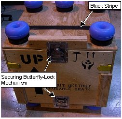
- Check that the SW1 is at Operation position.
Figure 18. Operation Position 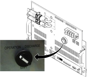
Finalization
Procedure
- Restore the Power. Refer to Lockout / Tagout for MDP(Main Disconnect Panel) or Facility PDU .
- Refill Coolant. Refer to Refill Coolant after replacement of SRFD3, XFA, or XFD-PS.
- Perform Signal to Noise - Head Scan.