
- SIGNA MR355 / SIGNA MR360
- Service Manual
- 5856356-3EN Revision 5.0
- Basic Service Documentation. Copyright General Electric Company.
- 00000018WIA3024FF20GYZ
- id_131069951.3
- Jul 5, 2019 10:25:10 PM
Cabinet Interface Board
Prerequisites
| Required persons | Preliminary requirements | Procedure | Finalization |
|---|---|---|---|
| 1 | Not Applicable | 120 minutes | 15 minutes |
| Item | Quantity | Effectivity | Part number | Manufacturer |
|---|---|---|---|---|
| Non Magnetic Tool Set | 1 | - | - | - |
| Item | Quantity | Effectivity | Part number | Manufacturer |
|---|---|---|---|---|
| Cabinet Interface Board (Refer to Illustrated Parts) | 1 | - | - | - |
| ||||||||
| Condition | Reference | Effectivity |
|---|---|---|
|
PDU must be turned OFF. Refer to Lockout / Tagout for PDU in System Cabinet. | - | - |
Procedure
- Remove screws fixing Cabinet Interface Board and Penetration
Panel.Note:
If it is difficult to remove cables or screws because of conflict of blower power cables, remove the blower power cables for easy operation. Do not forget to restore after replacement.
Figure 1. Cabinet Interface Board Cables 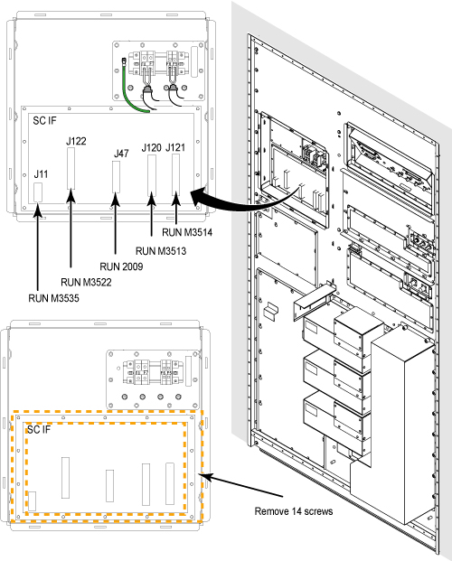
- Slowly rotate the SCIF board and first disconnect the cable
connected with J108 at the rear side of SCIF board.
Figure 2. Disconnect J108 cable 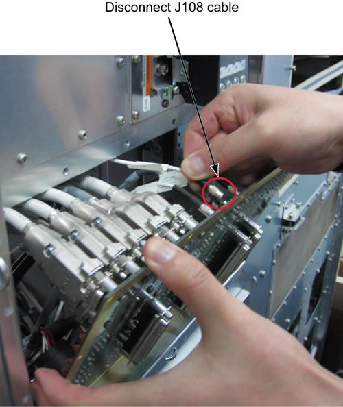
- Access the rear panel cables from Magnet Room side and remove
the cables from defective Cabinet Interface Board.
Figure 3. Remove cables from Cabinet Interface Board 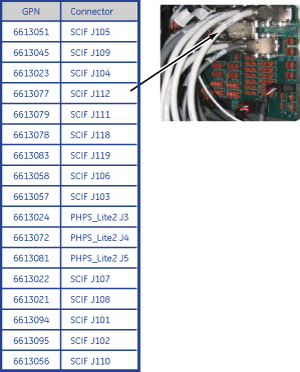
- Remove Cabinet Interface Board from Penetration Panel.
Figure 4. Remove Cabinet Interface Board 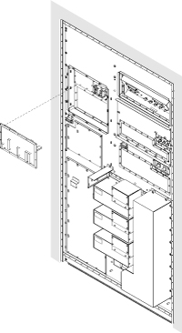
Finalization
- Restore the Power. Refer to Lockout / Tagout for PDU in System Cabinet.
- Perform Signal to Noise - Head Scan.