
- SIGNA MR355 / SIGNA MR360
- Service Manual
- 5856356-3EN Revision 5.0
- Basic Service Documentation. Copyright General Electric Company.
- 00000018WIA30B6FF20GYZ
- id_131069671.3
- Jul 6, 2019 12:03:29 AM
Control Board for XFA
Prerequisites
| Required persons | Preliminary requirements | Procedure | Finalization |
|---|---|---|---|
| 1 | Not Applicable | 15 minutes | 35 minutes |
| Item | Quantity | Effectivity | Part number | Manufacturer |
|---|---|---|---|---|
| Standard Tool | 1 | - | - | - |
| Item | Quantity | Effectivity | Part number | Manufacturer |
|---|---|---|---|---|
| Control Board for XFA (Refer to Illustrated Parts) | 1 | - | - | - |
| ||||
| Condition | Reference | Effectivity |
|---|---|---|
|
System Power must be turned OFF. Refer to System Cabinet PDU Main Breaker LOTO Procedure. | - | - |
Procedure
- Remove the cabinet leak sensor assy by loosening 6 screws.
Figure 1. Remove Leak Sensor 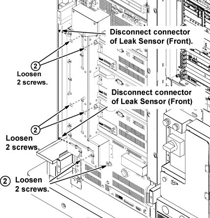
- Open two extractor levers, and remove control board from XFA. Note:
The control board can be removed/inserted to the socket by lifting up a little.
Figure 2. control board 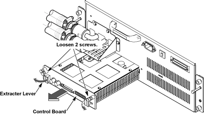
Finalization
Procedure
- Restore the Power. Refer to System Cabinet PDU Main Breaker LOTO Procedure.
- To adjust DC Offsets, refer to DC Offset Adjustment.
- Perform [TPS Reset].
- Perform DQA Tool.
- Perform Signal to Noise - Head Scan.