- id_12374926
- Version: 1.7
- Date: Jul 5, 2019 10:03:33 PM
Transient Detection Module (TDM) Replacement
Prerequisites
| Required persons | Preliminary requirements | Procedure | Finalization |
|---|---|---|---|
| 1 | Not Applicable | 30 minutes | 30 minutes |
| Item | Quantity | Effectivity | Part number | Manufacturer |
|---|---|---|---|---|
| Non-Magnetic Service Tool Kit | 1 | - |
5112581 |
- |
| Item | Quantity | Effectivity | Part number | Manufacturer |
|---|---|---|---|---|
| Transient Detection Module (TDM) | 1 | - |
Refer to FRU Manual |
- |
|

Removing TDM
Procedure
- Perform LOTO on the PEN cabinet. See the MR Service Safety Manual, PN 5452735.
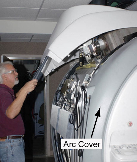
- Remove the magnet side cover to access the TDM. See Side Cover Removal and Installation.
Figure 1. Removing Magnet Side Cover
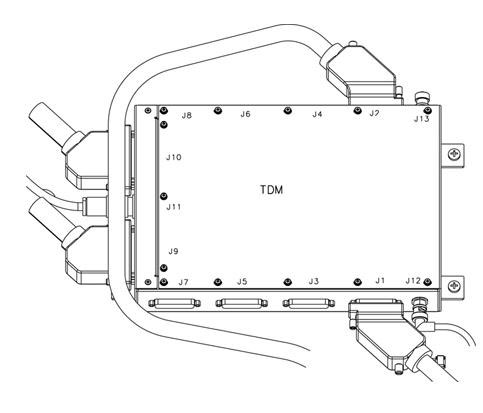
- Disconnect all cables connected to the TDM.note:
Remove J1 before you remove J12 in order to prevent damage to the end of the cable connected to J12.
Figure 2. TDM Cable Connections
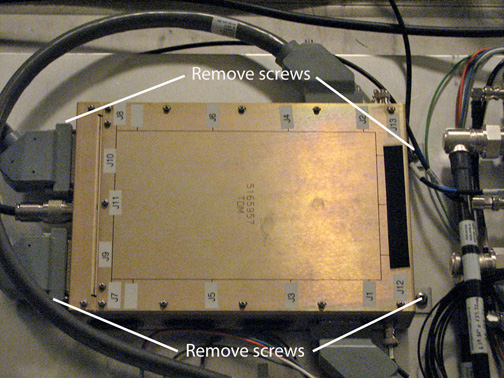
- Remove the four screws holding the TDM to the magnet.
Figure 3. Remove TDM Screws
 caution
- While carrying the module out of the magnet room, stay as far away from the magnet as possible.
Installing TDM
Procedure
- caution
- While carrying the module into the magnet room, stay as far away from the magnet as possible.
- Secure the module to the magnet by tightening the four screws provided.
- Attach all cables that were previously removed. See Figure 2.note:
To prevent damage to the cables, connect J12 before you connect J1.
- Replace the side cover.
- Remove LOTO from the PEN cabinet. See the MR Service Safety Manual, PN 5452735.
Finalization
Procedure
- Run TNS Datapath Diagnostics to confirm there are no remaining issues.
- Run a test scan to make sure the system is functional. See Check Scan.