- id_13106536
- Version: 3.5
- Date: Feb 10, 2020 9:35:29 AM
Dock centering and dock hook tension adjustment
Prerequisites
| Personnel requirements | |||
|---|---|---|---|
| Required persons | Preliminary requirements | Procedure | Finalization |
| 2 | - | 45 minutes | - |
| Tools and test equipment | |||
|---|---|---|---|
| Item | Quantity | Part number | Manufacturer |
| Nonmagnetic tool kit | 1 |
5112581 |
- |
| MRCv Tool Kit 1.5T | 1 | 5182417 | - |
| MRCv Tool Kit 3.0T | 1 | 5182417-2 | - |
| Consumables | |||
|---|---|---|---|
| Item | Quantity | Part number | Manufacturer |
| 11.0 mm washers | varies | - | - |
|
This dock adjustment procedure is required to properly align the cradle to the bridge in both the Z and X directions. Proper dock alignment ensures smooth travel of the cradle and protects table components from premature wear.
Dock centering
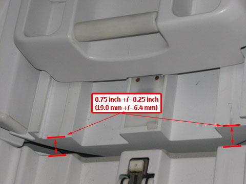
- The gap between the leading edge of the cradle top and the front of the bridge must be 0.75 inch ±0.25 inch (19.0 mm ±6.4 mm). This ensures that the gap is narrow enough to allow for smooth travel, but large enough to avoid rubbing on covers or bridge and to avoid pinch hazard. See Figure 1.
- The dock assembly must be square to the bridge, so the axis of the cradle travel is the same for both the patient table and bridge.
- The bosses of the dock and the patient table must align to ensure proper rotary pump alignment.
Longitudinal adjustment
Procedure
- With the patient table docked, measure the distance from the patient table top to the front of the magnet bridge. The distance should be 0.75 inch ±0.25 inch (19.0 mm ±6.4 mm). Also, the distance from the patient table top to the front of the magnet bridge should be equal so the patient table top is colinear with the bridge.
Figure 1. Table dock measurement
- If adjustment is required:
- Follow the precautions listed in Dock Removal and Reinstallation when you are working with the dock.
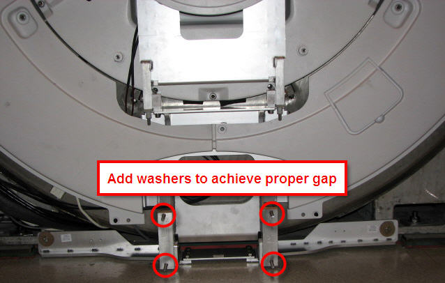
- Add or remove washers at the dock assembly and measure until the proper gap is achieved.
Figure 2. Dock positioning adjustment
Lateral adjustment
Procedure
- Raise the table to maximum height using the UP foot pedal.
- Dock the patient table.
- Drive the cradle all the way into the bore. Do the dock lateral adjustment until the vertical wheel tracks are aligned right and left.
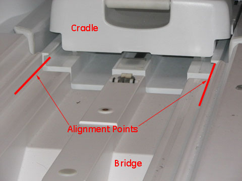
- Check the alignment of the patient table against the bridge (left-to-right alignment only). Use the vertical wheel tracks to line up the table with the magnet bridge. Use the inner edge corners of the table and magnet bridge as alignment points. Height is adjusted using the Table Top Height Adjustment procedure.
Figure 3. Cable track alignment points
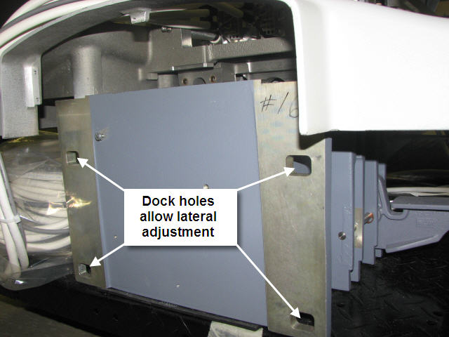
- If adjustment is required, loosen the nuts on the dock bracket (shown in Figure 2) to the rear of the dock (shown in Figure 4). Move the dock left or right to the proper position so the wheel tracks line up.
Figure 4. Rear of dock and lateral bolt holes
Boss alignment
Procedure
- Dock the patient table.
- Inspect the bosses on both sides of the table and dock for concentric alignment.
Figure 5. Inspect bosses for concentric alignment
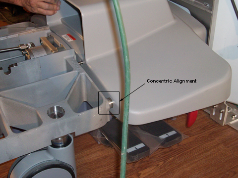 note: A missing front table cover, as shown in Figure 5 may result in 16-channel systems reporting a 32-channel electrical connector not attached. When adjustment is complete, replace the front cover to prevent these errors.
 - Adjust the table casters as necessary to ensure concentric alignment in the vertical direction. The final distance between the dock boss and the table boss should be ±1.0 mm. (See Leveling Patient Table.)
Dock hook tension adjustment
Procedure
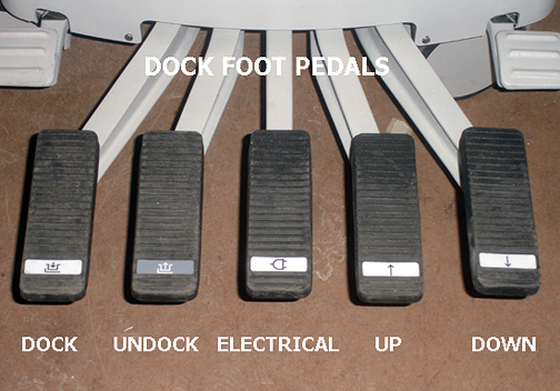
- Dock the patient table using the DOCK pedal, paying close attention to the force required to engage the docking mechanism. (Initial docking should not require significant force to depress the dock pedal.)
Figure 6. Foot Pedals
- Note the following dock pedal conditions:When depressing the dock pedal, if the force needed was other than a crisp snap at the bottom of the pedal stroke, then one of two conditions are in effect and action is required:
- Too loose - Minimal or no force at all was needed to reach the bottom of the stroke.
- Too tight - Considerable to significant force was needed to reach the bottom of the stroke, resulting in a hard, strong snap at the end.note: Both conditions (too loose and too tight) require the same action of loosening the set screw.
 caution
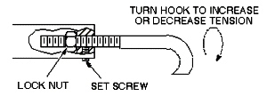
- Loosen the set screw. (See Figure 7.)
- notice
- Adjust the hook by loosening the lock nut at the rear of the hook, and turning the hook clockwise (to tighten) or counterclockwise (to loosen). One full turn is equal to 1/16 inch.note: The patient table must be undocked for all hook adjustments. Make the appropriate number of turns on the hook, retighten the lock nut, and then retest the force needed on the dock pedal when docking the table.
Figure 7. Dock hook tension adjustment
- Repeat Step 4 until a crisp snap of the hook is achieved when docking the patient table.
- Re-tighten the set screw.
 |
 |
Finalization
Finalization
- Replace all covers.
- Dock the table.
- Confirm that the cradle release functions properly.
- Confirm that the LPCA connects to the cradle and that the cradle can move into the bore.
- Perform Patient Table Movement Verification.