- id_13106738
- Version: 3.1
- Date: Jan 17, 2020 10:59:25 AM
Laser light alignment
Prerequisites
| Required persons | Preliminary requirements | Procedure | Finalization |
|---|---|---|---|
| 1 | Not applicable | 30 minutes | Not applicable |
| Item | Quantity | Effectivity | Part number | Manufacturer |
|---|---|---|---|---|
| Non-Ferrous Allen Wrench Set | 1 | - | - | - |
| Non-Ferrous Flat Blade Screwdriver | 1 | - | - | - |
System with In room monitor
Procedure
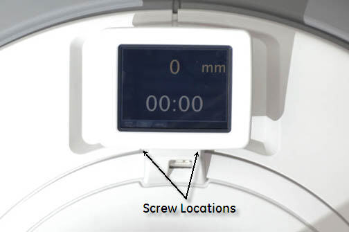
- Remove the laser light lens cover (top of magnet) by removing
two (2) screws Figure 1.
Figure 1. Remove laser light cover
- Press the Alignment button on the control panel to turn on the laser light.
 warning
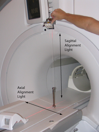
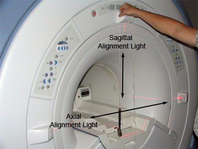
- Run a plumb line, using a non-magnetic device, down from the Sagittal and axial (top) laser lights. Verify that both the Sagittal and Axial alignment lights are aiming straight down and aligned with the string Figure 2.
Figure 2. Running a plumb line
- If adjustments are needed, loosen the flat head screws and move
the joysticks until the Axial and Sagittal laser lights are aligned
properly. See Figure 4.note: Ensure to tighten the head screws after making the required adjustments.
Figure 3. Adjusting laser lights
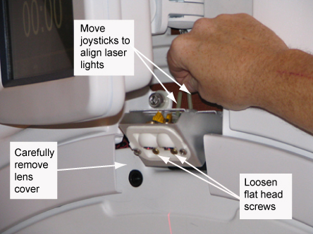
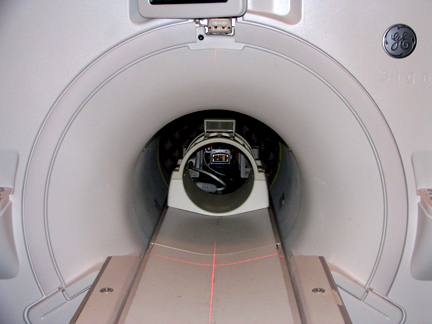
Figure 4. Properly aligned laser lights
- Replace the laser light lens cover.
 |
System without In room monitor
Procedure
- Remove the Lens cover for the laser lights.
- Turn the laser lights on.
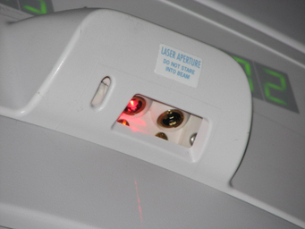
Figure 5. Laser light configuration
- warning
- Run a plumb line, using a non-magnetic device and string down
from the Sagittal and Axial (Top) laser light. Verify that both the
Sagittal and Axial Alignment Lights are aiming straight down (see Figure 6, Figure 7 and Figure 8).
Figure 6. Alignment light adjustment
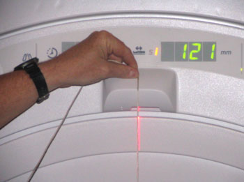
- When adjusting the Sagittal Alignment Light, the plumb line
must run down the front of the Laser Light cover, as shown in the
illustration below. The Sagittal Alignment light runs parallel to
the magnet in the center of the bore.
Verify that string is properly aligned with the beam. Then adjust Sagittal Alignment Light. This light runs parallel to the magnet bore.
Figure 7. Sagittal alignment light
- When adjusting the axial alignment light, the plumb line must run down the side of the laser light cover, as shown in the illustration below. The axial light runs perpendicular to the magnet bore.
Figure 8. Axial alignment light
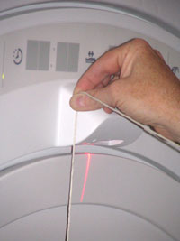
Verify that string is properly aligned with the beam. Then adjust axial alignment light. This light runs perpendicular to the magnet bore.
- If adjustments are needed, remove the upper display by carefully
prying the cover off. See Figure 9 and Figure 10.
Figure 9. Axial and sagital light adjustment
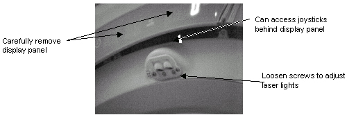
Figure 10. Upper laser
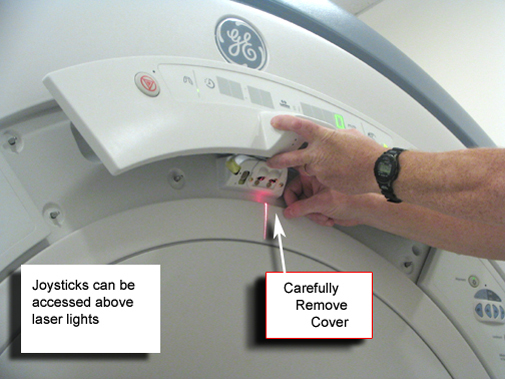
- For dual laser light configuration, both joysticks will need adjustment. For the single laser light configuration, only adjust light on the left side.
|
Finalization
Finalization
No finalization steps.