The DQA tool determines proper gradient polarity and proper gradient wiring by scanning a series of axial and coronal images of the DQA III phantom.
Prerequisites
Personnel requirements
Required persons
Preliminary requirements
Procedure
Finalization
1
-
30 minutes (varies)
10 minutes
Table 1 Tools and test equipment
Item
Quantity
Effectivity
Part number
Manufacturer
DQA III Phantom
1
-
2321556
-
Service Filler Panel
2
Curved table
5344577
-
1.5T TR Split-Top Head Coil
1
-
5182594
-
Condition
Reference
Effectivity
Laser light alignment completed.
-
-
Safety
Before working in any GE Healthcare MR suite or performing any GE Healthcare service procedure, you must:
Have read and understood all hazard conditions and safety requirements in the latest revision of the GE Healthcare MR Service Safety Manual (5452735).
Have successfully completed all relevant GE Healthcare Environmental Health and Safety (EHS) courses (or for non-GE employees, equivalent workplace training courses).
Comply with all site-specific training and workplace safety requirements.
If you have any safety concerns at any time, do not begin work or immediately stop work and move to a safe location. Immediately contact your supervisor or site safety officer for instructions on how to proceed.
The DQA tool determines proper gradient polarity (positive to positive and negative to negative) and proper gradient wiring (X amp drives X coil, Y amp drives Y coil, Z amp drives Z coil) by scanning a series of axial and coronal images of the DQA III phantom. The tool also verifies that the proper phantom is being used. After proper gradient orientation is confirmed, the tool adjusts for Z isocenter and gradient calibration. If Z iso adjustments or gradient calibration adjustments are required, the DQA tool performs the appropriate iterations to complete. Therefore, the DQA tool time to complete may vary.
Procedure
Verify that
Laser Light Alignment was completed. Pay close attention when positioning the alignment light on the phantom, because this procedure requires an accurate landmark.
(For curved tables) Insert the DQA III phantom into the head coil, and verify its orientation and levelness. Make sure the head coil is securely clamped to the table to avoid the coil moving out of position during table advance to isocenter.
note:Never use the touch-and-go landmarking strip when manually landmarking as part of a calibration tool procedure.
Landmark on the center line of the DQA III phantom. The laser must be in the middle of the black circumferential line on the phantom.
note:Never use the touch-and-go landmarking strip when manually landmarking as part of a calibration tool procedure.
Start the DQA tool:
(For non-proprietary mode) From the Common Service Desktop, select Calibration > DQA Calibration, then click Click here to start this tool.
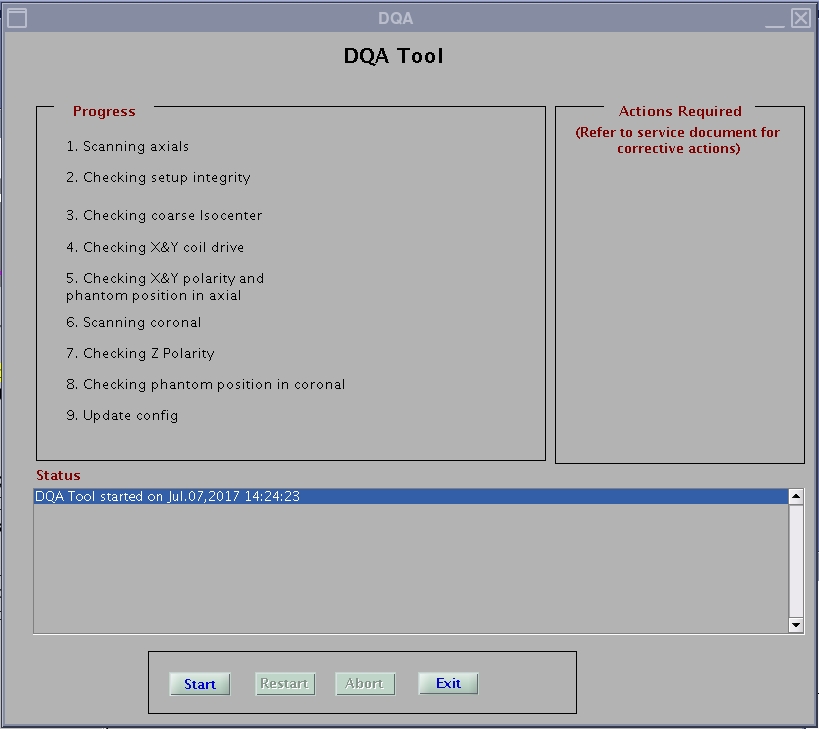
In the new window that displays, click Start.
Figure 1. DQA tool
All phantom images acquired during the DQA tool can be viewed in the browser. View these images if problems occur.
To stop the DQA tool without restarting it, click Abort at any time.
As the DQA tool progresses, the status displays in the Progress area. If problems are encountered, they display in the Actions Required area.
Figure 2. DQA screen with actions required
note: After resolving the issues in the Actions Required section, click Restart to restart the DQA tool.
A pop-up dialogue will ask if you want to update the config file with the new values.
After the tool successfully completes its tasks, click Exit.
Figure 3. Successful test
note: The finalization steps are included at the end of this procedure.
 To stop the DQA tool without restarting it, click Abort at any time.
 note: After resolving the issues in the Actions Required section, click Restart to restart the DQA tool.A pop-up dialogue will ask if you want to update the config file with the new values.
 note: The finalization steps are included at the end of this procedure.