Basic Service Documentation. Copyright General Electric Company.
Object ID: 00000018WIA30521730GYZ
Topic ID: id_2012034 Version: 4.0
Date: Feb 26, 2021 3:43:25 AM
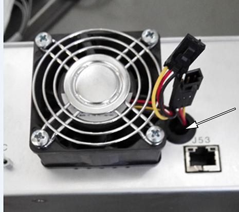
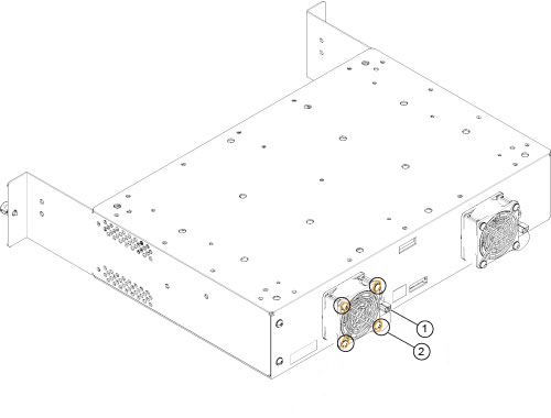
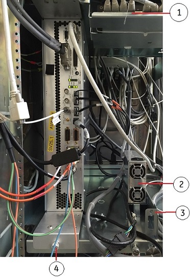
Removing the Integrated Control Engine (ICE) fan assembly
Removing the Integrated Control Engine (ICE) fan assembly from the System Cabinet.
Prerequisites
Personnel requirements
Required persons
Preliminary requirements
Procedure
Finalization
1
-
5 to 10 minutes
-
Tools and test equipment
Item
Quantity
Part number
Manufacturer
Nonmagnetic Titanium Service Tool Kit, Small Set
1 Kit
5113258
-
Nonmagnetic Titanium Service Tool Kit, Large Set
5112581
-
Procedure
Notice
Risk of ICN damage
The ICNs have software running on disk drives that can be corrupted if not shut down properly. Failure to properly power down an ICN can also result in premature ICN failure.
NEVER use the power button on the front to turn an ICN ON/OFF. Follow the procedure referenced below for removing power to the ICN chassis.
From the Common Service Desktop, turn off the ICN(s) (see ICN On/Off Procedure).

 Note: Hold the ICE carefully when you remove it so that it does not fall.